NaviGo Portal Help
Copyright © 2007-2012 Telogis, Inc. All rights reserved.
| Revision History | ||
|---|---|---|
| Revision 1.80 | Document generated on: Wed Jun 3 14:15:18 EDT 2015 | |
- Table of Contents
- Legal Notice-Terms of Your Use of this Document
- Overview
- Logging In to NaviGo Portal
- Navigating the Portal
- NaviGo Monitor
- NaviGo Event Viewer
- Driver Addresses
- Fuel Stations
- POI Editor
- NaviGo RoadManager
- Route Generator
- Tools
- Preferences
- Logging out of NaviGo Portal
Legal Notice-Terms of Your Use of this Document
There should be a written contract between Telogis, Inc. ("Telogis") and the company by which you are employed (hereinafter, "Company") that governs you and your Company's use of this Confidential/Proprietary Telogis document. In the unlikely event such contract does not exist or has expired, then the use of this document, including the information contained therein, by you, not only individually, but also as an employee and on behalf of your Company, is subject to the CONFIDENTIALITY AND NONDISCLOSURE provisions below. IF YOU OR YOUR COMPANY DOES NOT AGREE WITH THESE PROVISIONS, YOU AND YOUR COMPANY MUST IMMEDIATELY CEASE USING THIS DOCUMENT AND DESTROY IT.
CONFIDENTIALITY AND NONDISCLOSURE PROVISIONS
This document, including the information contained therein, constitutes the valuable confidential and proprietary information and property (hereinafter, "Confidential Information") of Telogis or its suppliers. Your use of this Confidential Information is subject to the following terms and conditions:
1. Non-Disclosure and Non-Use. Except as otherwise hereafter expressly permitted or consented to in writing by Telogis, you agree (i) to keep this Confidential Information strictly confidential, (ii) to use such Confidential Information solely in connection with an authorized use or evaluation of Telogis's services (hereinafter, "Purpose"), (iii) not to disclose such Confidential Information to any person or entity (except for the Company's employees, agents and contractors who have a bona fide need to know for the Purpose, are under a duty of non-disclosure with respect to such information and are acting for the sole benefit of the Company (collectively, "Representatives"), (iv) to protect such Confidential Information by using the highest degree of care to prevent the loss, theft or unauthorized dissemination or publication of such Confidential Information, (v) not to use the Confidential Information for you or your Company's product development or incorporate any such Confidential Information in any device, method, product, service or patent, or to use it to compete with Telogis, directly or indirectly or, except for the Purpose stated above, for you, your Company's or any third party's benefit at any time and (vi) not to copy, scrape, disassemble, modify, create derivative works of, translate, reverse engineer, store in a retrieval system, decompile or attempt to obtain the source code for, or any other information from or about, or create derivative works based on, the Confidential Information. You agree that such Confidential Information is and shall remain the proprietary and confidential information and property of Telogis and/or its suppliers. You agree to notify Telogis immediately upon discovery of any unauthorized use or disclosure of Confidential Information or any other breach of these provisions and will cooperate in every reasonable way to help Telogis regain possession of the Confidential Information and prevent its further unauthorized use or disclosure. Notwithstanding the above, you may disclose this Confidential Information to the extent that disclosure is required to be disclosed by law; provided that you use all reasonable efforts to provide Telogis with at least ten (10) days' prior written notice of such disclosure, you disclose only that portion of the Confidential Information that is legally required to be furnished, and you reasonably cooperate with Telogis in its efforts to obtain a protective order or other assurances from the applicable judicial or governmental entity that it will afford the Confidential Information confidential treatment. You further agree not to remove, alter, cover or distort any trademark, trade name, copyright or other proprietary rights notices, legends, symbols or labels appearing on or in this Confidential Information.
2. Return of Confidential Information. At Telogis's request, you shall cease use of this Confidential Information and shall deliver to Telogis all documents and other media (and all copies and reproductions of any of the foregoing) in your possession or control to the extent same contain the Confidential Information. Upon Telogis's request, you shall also certify in writing that all materials containing this Confidential Information have been either returned to Telogis or, if requested by Telogis, destroyed.
3. Disclaimer. TELOGIS PROVIDES THIS CONFIDENTIAL INFORMATION SOLELY ON AN "AS-IS" BASIS, WITHOUT ANY WARRANTIES OF ANY KIND, EXPRESS OR IMPLIED, INCLUDING WITHOUT LIMITATION ANY IMPLIED WARRANTY OR MECHANTABILITY OR FITNESS FOR PARTICULAR PURPOSE or duty to update or correct.
4. LIMITATION ON LIABILITY. In no event will Telogis be liable for any lost profits, data, software or information of any kind, for errors contained in this document or for any direct, consequential, special, indirect, incidental, punitive, exemplary or other damages that may arise through your or your Company's use of this Confidential Information, or pre-release, evaluation or beta test products or services supplied by Telogis. Telogis may make changes in the specifications/information contained in this document at any time without prior notice.
5. No License . All Confidential Information shall remain the sole property of Telogis. No license of any trademark, patent, copyright or any other intellectual property right of Telogis is either granted or implied by its disclosure of this Confidential Information to you.
6. Governing Law. This agreement shall be governed by the laws of the State of California without regard to any conflict of law provisions, and you consent to the exclusive jurisdiction of the courts of Orange County California in any action or proceeding instituted in connection with your use of this Confidential Information.
7. Miscellaneous Provisions. These provisions constitute the entire, exclusive, complete, and final agreement and understanding between you and Telogis relating to this Confidential Information. These provisions may not be amended unless it is in writing and signed by a an authorized officer of Telogis. If any of the above provisions are held invalid or unenforceable for any reason, such invalidity or unenforceability only shall attach to such provision and shall not affect or invalidate any other provision. Use of the Telogis services mentioned in this document is subject to Telogis's Terms of Use, a current version of which can be found at http://www.telogis.com/privacy-policy
Overview
What is NaviGo Portal?
NaviGo Portal is a web-based application that allows you to monitor and manage your NaviGo solution. Using NaviGo Portal, you can perform a wide variety of operations, such as:
generate new routes
view existing route results
resubmit route requests
view detailed event information
manage road modifiers
manage points of interest
manage fuel stations
manage driver address books
manage drivers
manage fleets
view usage reports
Some features and applications are only available to administrators and resellers. Read more about NaviGo Portal User Accounts.
NaviGo Portal Applications
To simplify things, NaviGo Portal's features have been divided into various applications (or add-ons).
Note: Not every application/add-on is enabled by default. Contact your Maptuit Sales Representative for more information about enabling features.
NaviGo Monitor: NaviGo Monitor is an application that allows you to view logs of route requests, and reports that are generated using log data. If you have NaviGo Compliance configured, you can view information about various NaviGo events such as feedback, searches, route requests, out of route / back to route events, position reports (and many more!)
Event Viewer: Allows you to view detailed event information.
Driver Addresses: Allows you to view and edit the fleet address book, which contains addresses saved by drivers.
Fuel Stations: Allows you to view and edit fuel stations, including fuel pricing information.
POI Editor: Allows you to manage points of interest (POIs).
Road Manager: Allows you to create, view, and edit road modifiers. Modifiers allow you to customize routing by favoring or avoiding certain areas of the road network.
Route Generator: Allows you to generate single or multi-stop routes using a variety of route parameters. You can also view an outline of any road modifiers encountered on a route.
Driver Management: The driver management application allows you to manage drivers using operations such as search, create, edit and delete.
Fleet Preferences: The fleet preferences application allows you to manage fleets, sub-fleets, routing profiles, portal users, and fleet defaults.
Usage Report: The usage report application allows you to obtain statistical information about NaviGo usage.
Supported Browsers
NaviGo Portal is tested and supported on the following browsers:
Internet Explorer 6
Note: Newer Maptuit features may not display properly on IE6.
Internet Explorer 7
Internet Explorer 8
Internet Explorer 9
Note: Any versions of Internet Explorer with Compatibility View enabled are not supported.
Firefox 3, 4, 8
Note: Other browsers and versions may work but are untested.
Browser Issues and Workarounds
The following browser incompatibility issues have been identified:
If an Internet Explorer v6 browser window is re-sized too small, the zoom and pan controls on the map are not displayed.
Share Your Feedback
If you have feedback about NaviGo Portal, please share it with us!
You can submit feedback by clicking Feedback on the menu at the top of the page. After you click Feedback, a screen is displayed that allows you to submit your feedback to us.
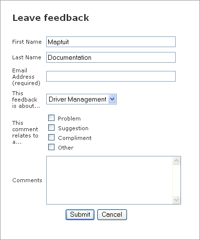
To submit your feedback, please fill out the fields on the form. When you are finished, click Submit to submit your feedback to us.
Logging In to NaviGo Portal
Before you can use Maptuit's NaviGo Portal, you must first login to the system using the login page.
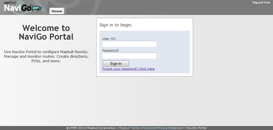
To login to Maptuit NaviGo Portal, enter your User ID and Password into the appropriate fields and click Sign In.
After logging in successfully, the NaviGo Portal home page will appear unless you have configured a different page to appear. You can modify your Preferences if you would like a different page to be displayed when you login. If you do not enter a valid User ID and Password, you will receive the following error: Account not found. User name must be in the form [accountname].[username]
If you are unable to login successfully, contact your fleet administrator or driver manager for assistance.
Recovering a Forgotten Password
If you have forgotten your password, you can recover it if your e-mail address is stored in the system.
If your e-mail address is not stored in the system, you must contact your fleet administrator or driver manager for assistance.
If your e-mail is stored in the system, you can recover your password by performing the following steps:
Click the Forgot your password? Click here link on the login page.
Type your login ID into the User ID field, and your e-mail address into the Email Address field.
Click Submit to recover your password, or Cancel to exit the password recovery screen.
If the ID or email address that you specified is not valid, you will receive the following error: That e-mail address could not be found. Contact your fleet administrator or driver manager for assistance.
If the operation is successful, your password is emailed to the address that you specified.
Check your email account to recover your password. You can now login to NaviGo Portal using the recovered password.
NaviGo Portal User Accounts
There are multiple types of NaviGo Portal accounts in order to efficiently manage user permissions. Each account type permits access to different features and functionality of NaviGo Portal.
The NaviGo Portal user accounts are:
Regular User
ability to use all applications that have been configured for that user account
Administrator
ability to manage drivers using the Driver Management tool
ability to manage portal users, sub-fleets and fleet defaults, using the Fleet Management tool
ability to access usage reports
Reseller
ability to perform all operations that can be performed by an Administrator
ability to change fleets using the fleet selection tool located in the upper right hand corner of NaviGo Portal
ability to manage fleets using the Fleet Management tool
Navigating the Portal
You can navigate NaviGo Portal by using the portal menus, or the portal home page.
Using the Portal Menus to Navigate
You can also access Maptuit NaviGo features by using the main menu:

In the figure above, there are actually two menus. The top menu allows you to control your Preferences, submit Feedback, view information About Maptuit NaviGo, and view Help information.
The main menu allows you to access the main NaviGo Portal functions: the Home page, NaviGo Monitor, Event Viewer, Driver Addresses, POI Editor, Road Manager, Route Generator, and NaviGo Portal Tools. If you hover over the Tools menu item, a drop down menu is displayed that contains the tools that are available.
Reseller users can manage multiple fleets. To change the fleet that you are currently managing in NaviGo Portal, simply click the Change button located in the top right hand corner, and then type the name of the fleet that you wish to load. NaviGo Portal will list matching fleets as you type. Simply click outside of the fleet selection tool, or press the ESC key to cancel the fleet selection. Or, when you see the fleet you wish to manage, click it. NaviGo Portal will confirm whether or not you wish to switch fleets.
Using the Portal Home Page to Navigate
You can select various NaviGo Portal applications by clicking on the application name or icon located on the home page (see below). You can access the home page at any time by clicking Home or by clicking the Maptuit NaviGo logo located in the top left hand corner of the screen.
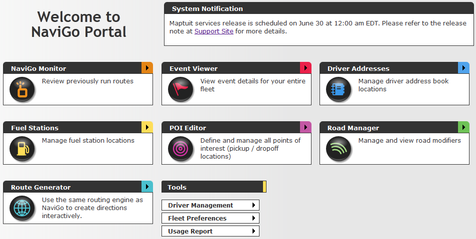
The home page contains a System Notification area that you can use to display helpful information. Please contact your customer support representative for help configuring this feature.
NaviGo Monitor
Overview
NaviGo Monitor is a NaviGo portal application that allows you to monitor fleets. You can view information about routes generated by fleet dispatch or requested by the driver. You can also view NaviGo Events if you have NaviGo Route Compliance or NaviGo Dispatch Compliance configured.
The NaviGo Monitor user interface is tab-based, which means you can perform multiple searches and view multiple details at the same time.
NaviGo Monitor allows you to view stored route traces, re-run route requests, and submit feedback about a route. NaviGo Monitor also allows you to view reports that are generated using the log data.
NaviGo Monitor logs provide you with helpful information about route requests that have been submitted to the system. For example, logs can be useful for recognizing when a route request has failed. A new log record is created every time a route request is submitted to the system.
Performing Searches
NaviGo Monitor provides a wide variety of search options so you can find log records more easily. NaviGo Monitor only returns search results if the log record matches all of the specified search criteria.
The most commonly used search fields are displayed at all times on the search form. Additional search options are available by clicking the Additional Options link located at the bottom of the search form.
The NaviGo Monitor search form looks like this:
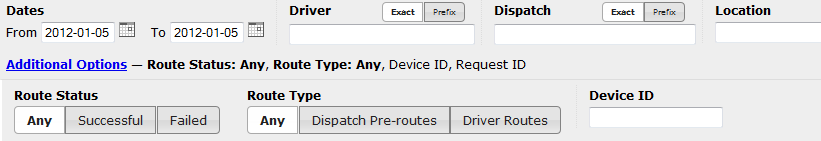
You can show or hide the additional options at any time by clicking the Additional Options link. For your convenience, a summary of the additional options are displayed so you can see what options are set even when the additional options panel is hidden. When a particular option is displayed in bold font, it means that the search option has been set to a value (e.g. Route Status: Any).
As stated previously, NaviGo Monitor only returns search results if the log record matches all of the specified search criteria. You can use the following search fields to narrow down your search results:
Dates: TheFromandTofields allow you to specify a start date and an end date by clicking the calendar and choosing a date. These filters allow you to limit the search results to records that occurred between two dates, before a particular date, or after a particular date. If specified, the search results will only contain route requests submitted during the specified date range. If both aFromandTodate are specified, theFromdate must be older than theTodate. The calendar allows you to search for records that are up to 45 days old.Driver: Enter a driver ID to limit the search results to one or more drivers. Leave blank to include all drivers. If theExactoption button is active (displayed with a white background), you must enter the full ID of the driver. If thePrefixoption button is active, you can enter just one or more leading characters. Any drivers whose IDs begin with those characters will be considered a match.Dispatch: Enter a dispatch ID to limit the search results to one or more dispatches. Leave blank to include all dispatches. If theExactoption button is active (displayed with a white background), you must enter the full ID of the dispatch. If thePrefixoption button is active, you can enter just one or more leading characters. Any dispatches whose IDs begin with those characters will be considered a match.Location: This filter allows you to limit search results to a specified location, such as a region, city, or street. If specified, the search results will only contain requests that partially match the location information in theRoutelinecolumn.Route Status: This filter allows you to limit search results to one of the following route statuses:All: Includes all routes regardless of status.Successful: Filters out route requests that have failed. Search results will only include successful routes.Failed: Filters out route requests that were successful. Search results will only include failed routes.
Device ID: This filter allows you to limit search results to a particular device. If specified, the search results will only contain requests submitted by the specified hardware device ID. Device IDs must be exact matches, but are not case sensitive. For example, a search for 123 will not match device ID 123456.Route Type: If your fleet is using NaviGo Dispatch Compliance, you can use this option to indicate whether you want to see all routes (Any), just routes that were generated using fleet dispatches (Dispatch Pre-routes), or just routes that were requested by the driver (Driver Routes).

After you have set your search criteria, click the Search button to view your results. Read more about Viewing and Understanding Search Results.
Performing Multiple Searches
NaviGo Monitor allows you to perform multiple searches at one time.
You can add a new search at any time by clicking the New Search tab.
After you click New Search, a new search tab appears.
For example, there are 3 searches in progress in the figure below:
To view a different search tab, click the tab that you wish to view.
You can close a tab at any time by clicking the X button located on the tab. The first search tab cannot be closed.
Viewing and Understanding Search Results
Search results will not appear on the screen until you have performed a search. Read more about Performing Searches using NaviGo Monitor.
After a search has been performed, NaviGo Monitor looks something like this:
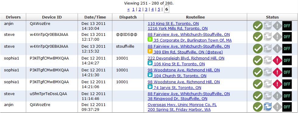
Each record contains the following information:
Driver: Indicates the ID of the driver that submitted the request.Device ID: Indicates the ID of the hardware device that submitted the request.Date/Time: Indicates the date and time that the request was submitted.Dispatch: Indicates the dispatch ID, if applicable.Routeline: Indicates the start point and end point of the requested route. Simply click the routeline link to view detailed information about the record.The following dispatch stop type icons may appear in the Routeline column beside the stop address:
The green
Dicon indicates that the stop is a drop off (or delivery) location.The orange
Picon indicates that the stop is a pickup location.The blue fuel tank icon indicates that the stop is a fuel location.
The purple
Oicon indicates that the stop type is Other, which means the stop type was set to Other or the dispatch stop was created without a stop type.If there is no dispatch stop type icon displayed, the route was requested from the Where To: Location Search screen in NaviGo.
The
Routelinecolumn may also outline error information. For example, Request Error: [RS] At least one route endpoint is inaccessible.
Status: Indicates status information using a variety of icons (see below).The following Route Status icons indicate whether the route was generated successfully or not:
The green checkmark icon indicates that the route was generated successfully.
The red X icon indicates that the route generation failed.
The Dispatch Route icon indicates whether the route was generated using a fleet dispatch:
This icon will only appear for fleets using NaviGo Dispatch Compliance.
The following Reroute Status icons indicate whether the route was generated as a result of a re-route operation:
The grey circular arrow icon indicates that the route was generated normally (not due to a reroute operation).
The blue circular arrow icon indicates that the route was generated due to a reroute operation.
The Onboard Back to Route icon indicates that the route was generated by an onboard back-to-route request:
This icon will only appear for routes generated using NaviGo Version 4 or higher.
The following HazMat Status icons indicate whether a HazMat route was requested, and whether a HazMat route could be successfully generated:
The gray exclamation mark icon indicates that a HazMat route was not requested.
The red exclamation mark icon indicates that a HazMat route was requested, and a HazMat compliant route was successfully generated.
The red exclamation mark icon (with the yellow arrow) indicates that a HazMat route was requested, but a fallback route was generated instead of a fully HazMat compliant route.
The following icons indicate whether the route was generated using the onboard or offboard routing engine:
The On icon indicates that the route was generated using the onboard routing engine.
The Off icon indicates that the route was generated using the offboard routing engine.
Note: These icons only appear for routes generated using NaviGo Version 4 or higher.

View Details
You can view the details about a route by clicking the route link.
A Details tab opens and displays information about the route, including the original route trace.
Note: NaviGo Monitor provides a tab-based interface, which means you can have multiple Details tabs open at the same time. Simply click the tab that you wish to view. To close a tab, click the X icon located on the tab that you wish to close.
The Details tab looks like this:
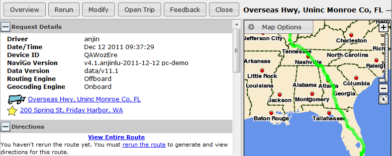
There are four buttons displayed at the top of the Details page. These buttons allow you to perform the following operations:
Overview: Refreshes the map, providing an overview of the entire route.
Rerun: Submits the stored route request as a new request. The resulting route trace is displayed on the map, and the corresponding text directions are displayed. If any route parameters have changed since the original route request, your new route results may differ from the original route results.
Note: The Rerun button and the
Directionspanel do not appear on the screen if the routeline includes a stop that is [unknown]. You cannot generate directions if one of the stops cannot be located.Modify: Opens the route in the Route Generator application so you can modify the route.
Open Trip: Opens the route in the Event Viewer application so you can view event details. This button is only available for routes generated using the offboard routing server.
Feedback: Allows you to submit feedback about the route. For example, please let us know if you feel a generated route is not optimal, or if it is incorrect for any reason.
Close: Allows you to close the Details tab.
Note: You do not have to close the tab. You can leave the tab open and continue using other tabs. You can also close tabs at any time by clicking the X on the tab that you wish to close.
The left-hand side of the screen provides information about route, including Request Details and Directions. For your viewing convenience, the left side panel is resizable. Simply click and drag the border of the panel to adjust the horizontal size.
Request Details
The request details are displayed on the left hand side of the screen. The request details provide the following information about the request:
Driver: Indicates the driver ID of the driver that submitted the request.Device ID: Indicates the ID of the device that submitted the request.Date/Time: Indicates the date and time that the request was received.Dispatch: Indicates the ID of the dispatch.Note: This information does not appear if the route is not associated with a dispatch.
NaviGo Version: The version number of NaviGo client software used to generate the route request.Data Version: The version of the dataset used to generate the route.Routing Engine: Indicates whether the onboard or offboard routing engine was used to generate the route.Geocoding Engine: Indicates whether the onboard or offboard geocoding engine was used to geocode the locations.HazMat Info: Indicates the HazMat classes that were used to generate a HazMat-compliant route. If a fallback route was provided instead, it is indicated here.Note: This information does not appear if a HazMat route was not requested.
The origin and destination of the requested route are displayed as links. You can click these links to zoom in on the map at that location.
Directions
The Directions panel allows you to view the step by step directions of the route.
The route directions do not appear on the Details page until you have rerun the route. To rerun the route, simply click the Rerun button located at the top of the screen.
Note: The Rerun button and the Directions panel do not appear on the screen if the routeline includes a stop that is [unknown]. You cannot generate directions if one of the stops cannot be located.
You can click the View Entire Route link at any time to automatically zoom and re-center the map on the route.
Map Options
The Map Options panel allows you to control the elements and information that are displayed on the map. The Map Options panel is located in the top left hand corner of the map. Click the Map Options button to open or close the Map Options panel.

Note: To enhance map performance, some map options are only available at a minimum scale level. If you are zoomed out too far for a particular map option, the option is grayed out and no longer available. After you zoom in to a certain level, the option will become active again.
The following map options are available.
Table 1. Map Options
| Option | Description |
|---|---|
| Points of Interest | Displays your fleet's points of interest on the map. These do not include NAVTEQ POIs or fuel POIs. POIs are displayed on the map using a bullseye icon. Points of interest can be viewed at map scale levels 7 and above. |
| Yard Shape | Displays the location of yards. Yards appear on the map in blue. Yard shapes can be viewed on the map at scale levels 6 and above. |
| Truck Road Network | Displays the truck road network. Truck roads appear on the map in green. The truck road network can be viewed on the map at scale levels 7 and above. |
| Aerial Imagery | Displays the map using aerial imagery. When this option is enabled, you can use the slide bar to control the transparency of the aerial imagery. Aerial imagery can be displayed at all map scale levels but is only available for maps of the USA and some portions of Canada. |
| NaviGo Events | Represents NaviGo events on the map using event markers. Once this option is enabled, you can control which event types are represented. NaviGo events can be displayed at all map scale levels. NaviGo events are displayed using colored markers, which appear differently depending on map scale level. |
| Truck Restrictions | Displays NAVTEQ truck restrictions on the map. Only those that apply to STAA-approved, non-HazMat roads are shown. Truck restrictions, like other road modifiers, appear in brown on the map. Truck restrictions can be viewed at map scale levels 7 and above. |
| NAVTEQ HazMat | Displays NAVTEQ's HazMat-designated and HazMat-restricted road segments on the map. NAVTEQ's HazMat road segements can be viewed at map scale levels 7 and above. |
| Maptuit Global | Displays Maptuit's global road modifiers on the map. Maptuit's modifiers are drawn from our data sources, including feedback from drivers. Maptuit global modifiers can be viewed at map scale levels 7 and above. |
| Maptuit Global HazMat | Displays Maptuit's HazMat-designated and HazMat-restricted road segments on the map. Maptuit's HazMat road segements can be viewed at map scale levels 7 and above. |
| Fleet Modifiers | Displays your fleet's road modifiers on the map. Your fleet's modifiers can be viewed on the map at scale levels 7 and above. |


NaviGo Event Viewer
Overview
Event Viewer is a NaviGo Portal application that allows you to retrieve detailed event information for your fleet. NaviGo Event Viewer is available for fleets using NaviGo Route Compliance or NaviGo Dispatch Compliance.
Events represent changes in the status of a vehicle. They can range from route events such as starting or completing a route to compliance events such as deviating from a route or returning to a route. Events also include logging in or out, searching for a route, losing a GPS connection, and many more.
For a complete list of event types, see Event Types.
If you have NaviGo Route Compliance or NaviGo Dispatch Compliance configured for your fleet, you can use the Event Viewer to retrieve event information for a particular driver or for a particular dispatch.
The Event Viewer user interface is tab-based, which means you can view different event information on different pages.
Retrieving Event Information
You can retrieve event information for a particular driver or for a particular dispatch.
Search by Driver
To retrieve event information for a particular driver, follow these steps:
Click the
Driverstab.From the Drivers page, enter the driver ID in the
Driverfield, or leave it blank to include all drivers.Note: You can enter the full ID or just a few characters. Any IDs that include those characters will be considered a match.
Specify a date range using the
Datescontrols. You can enter the date directly or click the Calendar icon and choose a date.Optionally, you can further narrow the results by specifying a unit ID.
Click the Search button to begin the search. A list of matching drivers with events in the specified date range will be displayed.
Within the search results, click the row displaying the ID of the driver whose events you want to view. (For a complete description of the search results, see Drivers Page Search Results.)
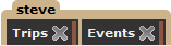
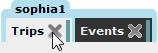
Two new tabs now appear for the driver on the Event Viewer screen: Trips and Events. To scroll through all the events for the selected driver, click the
Eventstab. To select a trip for the driver then view the events that occurred on that trip, click theTripstab.Color-coded tabs will appear for each driver you select from the Drivers page search results.

To remove a tab from the Event Viewer screen, click the X within the tab.
Search by Dispatch
To retrieve event information for a particular dispatch, follow these steps:
Click the
Dispatchestab.From the Dispatches page, enter the dispatch ID in the
Dispatchfield, or leave it blank to include all dispatches.Note: You can enter the full ID or just a few characters. Any IDs that include those characters will be considered a match.
Specify a date range using the
Datescontrols.Optionally, you can further narrow the results by specifying a driver ID or a unit ID.
Click the Search button to begin the search. A list of trips associated with matching dispatches in the specified date range will be displayed.
Within the search results, click the row displaying the trip whose events you want to view. (For a complete description of the search results, see Dispatches Page Search Results.)
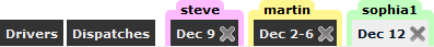
A trip tab now appears on the Event Viewer screen with the date(s) of the trip as the tab label. Click the tab to view the events that occurred on the trip you selected.
Separate tabs will appear for each trip you select from the Dispatches page search results.

Drivers Page
From the Drivers page in Event Viewer, you can search for drivers with events in a particular date range.
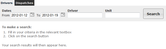
Search Options
The following search options are available from the Drivers page.
Table 2. Drivers Page Search Options
| Option | Description |
|---|---|
| Dates | The start date and end date of the range you want to search within. |
| Driver | The ID of the driver you want to search for. Leave blank to include all drivers. Instead of entering the full ID of the driver, you can enter just one or more characters. Any drivers whose IDs include those characters will be considered a match. |
| Unit | The ID of the unit. Leave blank to include all units. |
After you specify the search options, click Search to begin the search.
Drivers Page Search Results
When you click Search from the Drivers page, a list of matching drivers with events in the specified date range will be displayed.
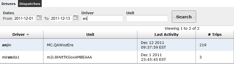
The following columns appear in the list.
Table 3. Drivers Page Search Results
| Column | Description |
|---|---|
| Driver | The ID of the driver. |
| Unit | The ID of the driver's unit. |
| Last Activity | The date and time of the last event recorded for the driver. |
| # Trips | The number of trips for the driver within the date range. |
| Planned | The planned distance of the trips for the driver within the date range. |
| Actual | The actual distance of the trips for the driver within the date range. |
| Difference | The difference between the planned and actual distance of the trips for the driver within the date range. |
| Variance % | The percentage variance between the planned and actual distance of the trips for the driver within the date range. |
To view events for a driver, click on the row displaying the driver's ID. Two new
tabs will appear for the driver on the Event Viewer screen: Trips and Events. To
scroll through all the events for the selected driver, click the
Events tab. To select a trip for the driver then view the
events that occurred on that trip, click the Trips tab.
Dispatches Page
From the Dispatches page, you can retrieve event information for a particular dispatch.
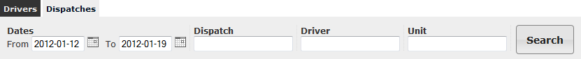
Search Options
The following search options are available from the Dispatches page.
Table 4. Dispatches Page Search Options
| Option | Description |
|---|---|
| Dates | The start date and end date of the range you want to search within. |
| Dispatch | The ID of the dispatch you want to search for. Leave blank to include all dispatches. Instead of entering the full ID of the dispatch, you can enter just one or more characters. Any dispatches whose IDs include those characters will be considered a match. |
| Driver | The ID of the driver you want to search for. Leave blank to include all drivers. Instead of entering the full ID of the driver, you can enter just one or more characters. Any drivers whose IDs include those characters will be considered a match. |
| Unit | The ID of the unit. Leave blank to include all units. |
Dispatches Page Search Results
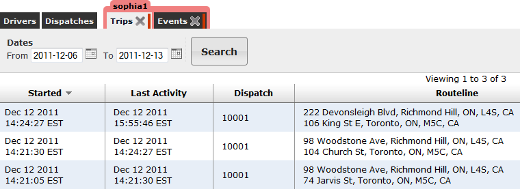
When you click Search from the Dispatches page, a list of trips associated with matching dispatches in the specified date range will be displayed.
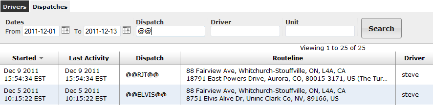
The following columns appear in the list.
Table 5. Dispatches Page Search Results
| Column | Description |
|---|---|
| Started | The date and time when the trip began. |
| Last Activity | The date and time of the last event recorded on the trip. |
| Dispatch | The dispatch ID. |
| Routeline | The starting location and destination of the requested route. |
| Driver | The ID of the driver. |
| Unit | The ID of the unit. |
| Planned | The planned distance of the trip. |
| Actual | The actual distance of the trip. |
| Difference | The difference between the planned and actual distance of the trip. |
To view events for a particular trip, click the row displaying the trip details. A trip tab will appear on the Event Viewer screen with the date(s) of the trip as a tab label. Click the tab to view the events that occurred on the trip.
Trips Page
From the Trips page, can view a list of trips for a particular driver within a specified date range. The Trips page appears when you click on a search result within the Drivers page.
You can change the date range and refresh the results by clicking the Search button.
When you click on a trip within the list, a trip tab will appear listing all the events that occurred on that trip. The date(s) of the trip will used as the tab label.
The following columns appear on the Trips page.
Table 6. Trips Page Results
| Column | Description |
|---|---|
| Started | The date and time when the trip began. |
| Last Activity | The date and time of the last event recorded on the trip. |
| Dispatch | The dispatch ID. |
| Routeline | The start point and end point of the requested route. |
| Planned | The planned distance of the trip. |
| Actual | The actual distance of the trip. |
| Diff | The difference between the planned and actual distance of the trip. |
| Status | The route status.
|
Events Page
From the Events page, you can view all the events for a driver within a particular date range. The Events page appears when you click on a search result within the Drivers page.
You can change the date range and refresh the results by clicking the Update button.
Events List
The events are listed in chronological order at the bottom of the page. The following columns appear within the events list.
Table 7. Events List Columns
| Column | Description |
|---|---|
| Date & Time | The time and date when the event took place. |
| Seq | The sequence number assigned to the event. Sequence numbers can be used to discern the order of events with identical timestamps. |
| Event | The event icon and description. The event icon indicates the type of event. For a description of the different event types, see Event Types. |
| Odometer | The vehicle's odometer reading at the time of the event. |
| Trip | The distance travelled since the route began. If this information is unavailable or inapplicable, a value of - will be displayed. |
| Remaining | The distance remaining in the trip. If this information is unavailable or inapplicable, a value of - will be displayed. |
| Proximity | The distance from the destination "as the crow flies". This distance is typically less than the remaining distance. If this information is unavailable or inapplicable, a value of - will be displayed. |
| Speed | The speed at which the vehicle was travelling. |
| Heading | The direction in which the vehicle was heading. |
| Text | Additional descriptive text for the event. |
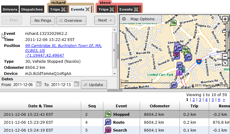
If you click on one of the event rows, the detailed information for that event appear in the details panel, and the map will shift to bring that event's marker into view.
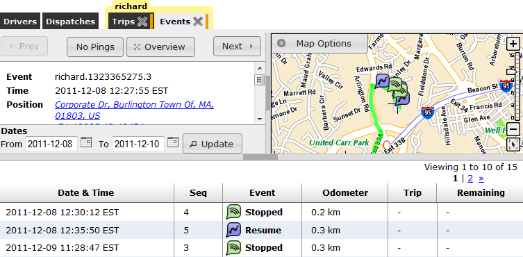
Details Panel
The details panel provides detail information on the event currently selected within the events list at the bottom.
Within the Details panel, you can click the Position or Destination links to center the map on the corresponding location. Clicking the Query button will run the destination query again and display the result. For Route and ReRoute events, you can open the route in NaviGo Monitor by clicking the Open route in NaviGo Monitor link.
The following buttons appear above the details panel.
Table 8. Details Panel Buttons
| Button | Description |
|---|---|
| Prev | Displays details for the previous event in the list. |
| No Pings/All Pings/Some Pings | By default, ping events are not included in the events list. To include ping events in the list, click the No Pings button until it changes to Some Pings or All Pings. Some Pings will only include a ping if the driver has moved approximately 3 miles (5 kilometres) since the last ping event.
|
| Overview | Displays the entire route within the map. |
| Next | Displays details the next event in the list. |
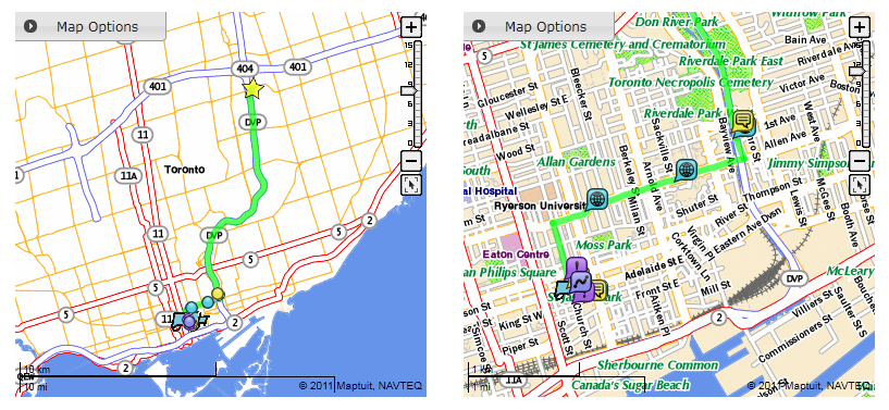
Map Panel
The map panel on the right displays markers showing the location of events. The map is centered on the currently selected event.
Within the map options, you can contol which event types are displayed in the map. For a description of the different event types, see Event Types.
Events are displayed using colored markers, with different colors for each event type. Event markers appear differently depending on map scale level. The following maps show event markers at different scale levels:
Controlling the Size of the Map Panel
To expand the map panel by reducing the height of the events list, drag the bar separating the two panels.
To maximize the map panel by hiding the events list, double click the dark rectangle within the separator bar.
To bring the events list back into view, double click the rectangle again.
Viewing Event on the Map
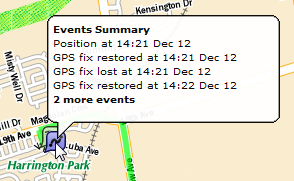
When you hover over an event marker on a map, a summary appears displaying information about those events.
Clicking on an event marker displays a chronological list of events for that location.
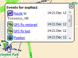
You can click on an event in the list to view more detailed information about the event.
Each event type may display slightly different information. See Event Types for a description of what appears for each event type.
To navigate between different events, you can use the following links:
Previous: Displays the detailed view of the event that occurred immediately before the current event.
Next: Displays the detailed view of the event that occurred immediately following the current event.
Back to list: Displays the list view of the NaviGo Events, sorted by time the events occurred.
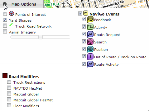
Map Options
The Map Options panel allows you to control the elements and information that are displayed on the map. The Map Options panel is located in the top left hand corner of the map. Click the Map Options button to open or close the Map Options panel.
Note: To enhance map performance, some map options are only available at a minimum scale level. If you are zoomed out too far for a particular map option, the option is grayed out and no longer available. After you zoom in to a certain level, the option will become active again.
The following map options are available.
Table 9. Map Options
| Options | Description |
|---|---|
| Points of Interest | Displays your fleet's points of interest on the map. These do not include NAVTEQ POIs or fuel POIs. POIs are displayed on the map using a bullseye icon. Points of interest can be viewed at map scale levels 7 and above. |
| Yard Shape | Displays the location of yards. Yards appear on the map in blue. Yard shapes can be viewed on the map at scale levels 6 and above. |
| Truck Road Network | Displays the truck road network. Truck roads appear on the map in green. The truck road network can be viewed on the map at scale levels 7 and above. |
| Aerial Imagery | Displays the map using aerial imagery. When this option is enabled, you can use the slide bar to control the transparency of the aerial imagery. Aerial imagery can be displayed at all map scale levels but is only available for maps of the USA and some portions of Canada. |
| NaviGo Events | Represents NaviGo events on the map using event markers. Once this option is enabled, you can control which event types are represented. NaviGo events can be displayed at all map scale levels. NaviGo events are displayed using colored markers, which appear differently depending on map scale level. For more information, see Viewing Events on a Map. |
| Truck Restrictions | Displays NAVTEQ truck restrictions on the map. Only those that apply to STAA-approved, non-HazMat roads are shown. Truck restrictions, like other road modifiers, appear in brown on the map. Truck restrictions can be viewed at map scale levels 7 and above. |
| NAVTEQ HazMat | Displays NAVTEQ's HazMat-designated and HazMat-restricted road segments on the map. NAVTEQ's HazMat road segments can be viewed at map scale levels 7 and above. |
| Maptuit Global | Displays Maptuit's global road modifiers on the map. Maptuit's modifiers are drawn from our data sources, including feedback from drivers. Maptuit global modifiers can be viewed at map scale levels 7 and above. |
| Maptuit Global HazMat | Displays Maptuit's HazMat-designated and HazMat-restricted road segments on the map. Maptuit's HazMat road segments can be viewed at map scale levels 7 and above. |
| Fleet Modifiers | Displays your fleet's road modifiers on the map. Your fleet's modifiers can be viewed on the map at scale levels 7 and above. |
Trip Pages
From a trip page, you can view all the events for a driver on a particular trip. Trip pages appear when you click on a trip within the Trips page, or within the search results on the Dispatches page.
The label at the top of each trip page corresponds to the date(s) of the trip.
For a description of the columns and buttons that appear on this page, see the Events page.
NaviGo Events
Events represent changes in the status of a vehicle, such as logging in or out, searching for a route, or completing a route.
If you have NaviGo Compliance configured for your fleet, you can use the NaviGo Event Viewer to view detailed event information.
Important: NaviGo Compliance must be configured prior to use. Contact your customer support representative to configure NaviGo Compliance.
NaviGo Event Types
Each event type is described in detail.
Feedback Events
Feedback events are triggered when a driver submits a feedback message in NaviGo. The detailed view of feedback events provides information about the date/time of the feedback, the driver who submitted the feedback, the location of the vehicle when the feedback was submitted, the feedback text, and the vehicle odometer reading.
You can view the full feedback message by clicking the feedback text summary link. The full feedback message displayed in a new dialog. Close the full feedback message dialog to return to the list of events.
Activity Events
Activity events provide information about driver activities. Activity events are triggered by the following actions:
Login/Logout: the driver logged in or logged out of NaviGoStopped: NaviGo detected that the vehicle stoppedMoving: NaviGo detected that the vehicle resumed movementHazMat: The driver requested a Hazmat route but accepted a non-compliant Hazmat routeGPS Lost: NaviGo detected that the GPS connection has been lost (NaviGo v3.3 and later)GPS Restored: NaviGo detected that the GPS connection has been restored (NaviGo v3.3 and later)
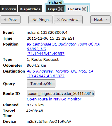
Route Request Events
Route request events provide information about route requested by a driver.
Route request events are triggered by the following actions:
Route: A route was generated in NaviGo using Maptuit's offboard routing serverReRoute: A route was generated in NaviGo using Maptuit's offboard routing server in response to a ReRoute requestRoute (Onboard): A route was generated in NaviGo using the onboard routing engineReRoute (Onboard): A route was generated in NaviGo using the onboard routing engine in response to a ReRoute requestBTR (Back to Route): A route was generated by Maptuit's offboard routing engine to return the driver to the original routeBTR (Onboard): A route was generated using the onboard routing engine to return the driver to the original routeDispatch Rt: A route was generated from a fleet dispatch.
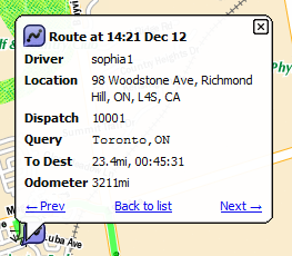
The detailed view of route events provides you with information about the date/time of the route request, the driver who submitted the route request, the location of the vehicle when the route request was submitted, the destination search query, distance to the destination, and the vehicle odometer reading.
While viewing the event details, you can also click the Open route in new tab link to view the route in the Route Generator application.
Search Events
Search events provide information about searches submitted by a driver on the WhereTo screen in NaviGo.
The detailed view of search events provides information about the date/time of the search, the driver who submitted the search, the location of the vehicle when the search request was submitted, the search query text, and the vehicle odometer reading.
Position Events
Position events (also known as pings) provide information about the position of a vehicle.
Position events are triggered on a configurable schedule so that you can see the path that the vehicle travelled.
The detailed view of position events provides you with information about the date/time of the position event, the driver who triggered the event, the location of the vehicle, and the vehicle odometer reading.
Out of Route / Back on Route (Compliance) Events
Out of Route / Back to Route events provide information about a driver's compliance with a generated route. Compliance events are triggered by the following actions:
OOR (Out of Route): The vehicle was detected off the routeBOR (Back on Route): The vehicle returned to the route
When viewing detailed information about compliance events, you can see the date/time of the compliance event, the driver that triggered the event, the location of the vehicle when the event occurred, the vehicle odometer reading, and the vehicle's direction of travel.
Route Activity Events
Route activity events provide information about the driver's progress along the route.
Route activity events are triggered by the following actions:
Start: The driver began driving the routeResume: The driver resumed the route, by clicking the Resume button in NaviGoArrival: The vehicle was detected at the destinationDispatch Evt: An event occurred within a route generated from a fleet dispatch. The event type will appear underDetailsin the detailed view.
The detailed view of route activity events provides you with information about the date/time of the event, the driver who triggered the event, the location of the vehicle, the vehicle's odometer reading, and the direction the vehicle was travelling in.
Driver Addresses
The Driver Addresses application allows you to manage the fleet address book.
The fleet address book is a collection of addresses that have been saved by drivers using NaviGo.
For example, a user can type save home on the Location Search screen while they are parked in their driveway, and NaviGo will save the current vehicle position to the driver address book.
In this scenario, the address is saved as home.
Saved addresses are actually stored as Points of Interest (POIs) in a separate POI database for the fleet. So, the tool that you will use to manage the driver addresses is the same tool that you use to manage your regular POIs. However, you must access the tool from the Driver Addresses screen instead of the POI Editor screen.
When you click the Driver Addresses tab, you will notice that the screen looks exactly the same as the POI Editor screen.
The tools work exactly the same, but there is one important difference:
The POI Editor screen allows you to manage your fleet POIs, while the Driver Addresses screen allows you to manage your fleet address book (which is actually a separate POI data set).
To learn more about using the POI Editor tool, please refer to the POI Editor section.
Then, click the Driver Addresses tab to start managing your fleet address book.
Note: You will not see your driver addresses when you are viewing the POI Editor screen. You must use the Driver Addresses screen to manage your fleet address book.
Fuel Stations
Maptuit's fuel services can provide information on fuel stations and their associated fuel prices within a customer-configurable radius or corridor along the truck's route. Fuel search results are returned based on the fuel stop's proximity to the vehicle's current location. In addition to selecting which fuel data feed a fleet wishes to use, customers also have the option of leveraging their own custom fuel network.
The Fuel Stations application allows you to manage fuel stations. These fuel stations are used when searching for fuel stations, or when generating routes with fuel planning.
Fuel stations are actually stored as Points of Interest (POIs) in a separate POI database for the fleet. So, the tool that you will use to manage the fuel stations is the same tool that you use to manage your regular POIs. However, you must access the tool from the Fuel Stations page instead of the POI Editor screen.
When you click the Fuel Stations tab, you will notice that the screen looks exactly the same as the POI Editor screen.
The tools work exactly the same, but there is one important difference:
The POI Editor screen allows you to manage your fleet POIs, while the Fuel Stations page allows you to manage your fleet's fuel stations (which is actually a separate POI data set).
To learn more about using the POI Editor tool, please refer to the POI Editor section.
Then, click the Fuel Stations tab to start managing your fleet's fuel stations.
Note: You will not see your fleet's fuel stations when you are viewing the POI Editor page. You must use the Fuel Stations page to manage your fleet address book.
POI Editor
Overview
POI Editor is a NaviGo Portal application that allows you to manage points of interest (POIs). You can create new POIs, search for POIs, edit existing POIs (including the geocode data), delete POIs, import batches of POIs, and export POI data.
POI Editor looks like this:
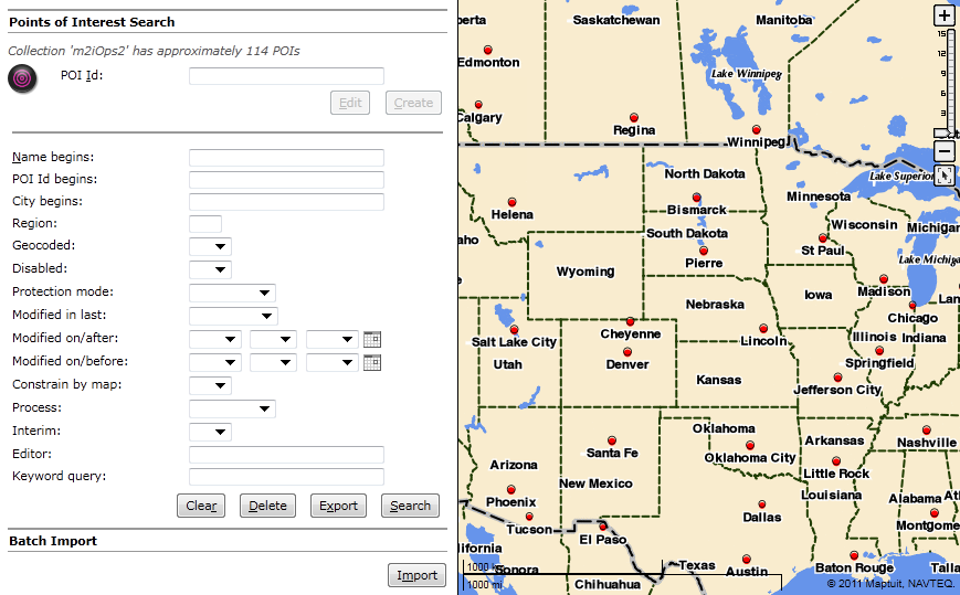
The main POI Editor screen provides direct access to many of POI Editor features, such as searching, deleting, and importing/exporting POIs. The main screen also provides you with an approximate number of POIs contained in the POI collection. The POI collections are indexed on a nightly basis. Therefore, this number is an approximation and may be slightly different than the actual number of POIs in the collection.
Searching for POIs
Before you can perform operations on POIs (edit, geocode, delete, etc.), you must first locate the POI using the search tool on the main POI Editor screen:
To quickly search for all POIs, simply click the Search button.
| Warning |
Searching the entire collection can take a long time depending on the size of the POI collection. |
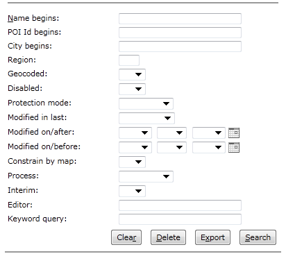
To narrow down your search results to a subset of POIs, you can use a variety of search filters. Simply enter information into the search filter fields and then click the Search button. You can click the Clear button at any time to clear all search filter fields.
Table 10. POI Search Filters
| Filter Name | Description | Acceptable Values |
|---|---|---|
Name begins | If specified, this search filter limits search results to POIs that have a Name beginning with the specified text. | This value can be set to a String. |
POI Id begins | If specified, this search filter limits search results to POIs that have an ID beginning with the specified text. | This value can be set to a String. |
City begins | If specified, this search filter limits search results to POIs that are located in a City name beginning with the specified text. | This value can be set to a string that is a city prefix (e.g. Washing). |
Region | If specified, this search filter limits search results to POIs located in the specified Region. | This value can be set to a String that is a valid region code (e.g. DC). |
Geocoded | If specified, this search filter limits search results to POIs that have the specified Geocode Status. | This search filter can be set to yes to return POIs that have been geocoded, or set to no to returns POIs that have not been geocoded. |
Disabled | If specified, this search filter limits search results to POIs that have the specified Disabled Status. | This search filter can be set to yes to return POIs that are disabled, or set to no to return POIs that have not been disabled. |
Protection mode | If specified, this search filter limits search results to POIs that have the specified Protection Mode. |
This filter can be set to one of the following values:
|
Modified in last | If specified, this search filter limits search results to POIs that have been modified within the specified time period. | Select a time period (e.g. |
Modified on/after | If specified, this search filter limits search results to POIs that have been modified on or after the specified date. | Choose a date using the calendar tool. |
Modified on/before | If specified, this search filter limits search results to POIs that have been modified on or before the specified date. | Choose a date using the calendar tool. |
Constrain by map | Defines whether or not to limit search results to POIs that are located in the current map extent (i.e. the map that is currently displayed on the screen). | This search filter can be set to yes to constrain the search to the map extent, or set to no to include POIs in all locations. The default value is no. |
Process | If specified, this search filter limits search results to POIs that were last modified via the specified process. |
This filter can be set to one of the following values:
|
Interim | If specified, this search filter limits search results to POIs that have the specified Interim status. POIs with an Interim status are generally those locations that have been flagged and should be revisited when data improves in the area. For example, the Interim status POIs will often be geocoded to an incorrect point because the actual location is not in the road network data. | This search filter can be set to yes to only include interim POIs in the search results. This filter can be set to no to only return POIs that have an interim status set to no. |
Editor | If specified, this search filter limits search results to POIs that were last edited by a person with a username beginning with the specified text. | This value can be set to a string. |
Keyword query | If specified, this search filter limits search results to POIs that contain the specified keyword.
| This value can be set to a String. |
Search Results
When the search is complete, POI Editor displays the POIs that match your search criteria. Here is an example of POI Search results.
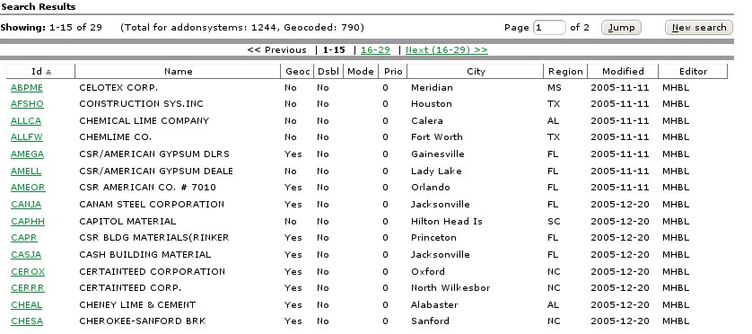
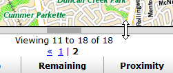
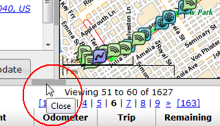
Your search results will display on the screen, with the first page of results displaying by default. If your search results include multiple pages, you can view different pages by clicking the page links or by entering a page number and clicking the Jump button to jump directly to that page. Sometimes your results will contain too many POIs to locate the one you are looking for. Try clicking the New Search button and using additional search parameters to narrow down your search results.
While viewing the search results, you can perform operations (e.g. edit, delete, geocode) on a POI by clicking the POI ID link.
Example 1. POI Search
Let's search for all POIs that have names beginning with the characters CN.
Simply set the Name Begins: search field to CN and then click the Search button.
Be careful! POI Names are different than POI IDs.
If you set the ID Begins: search field to the same thing, your results will differ.
If you want to edit the POI, click the POI ID link.
Creating POIs
You can create POIs one at a time using the interface, or you can import batches of POI data from a file. To import batches of POI data from a file, refer to the Importing POIs section.
To create a POI, you must provide an ID for the POI.
To begin creating a POI, enter an ID in the POI Id field on the main screen, and click the Create button to open the Create POI screen.
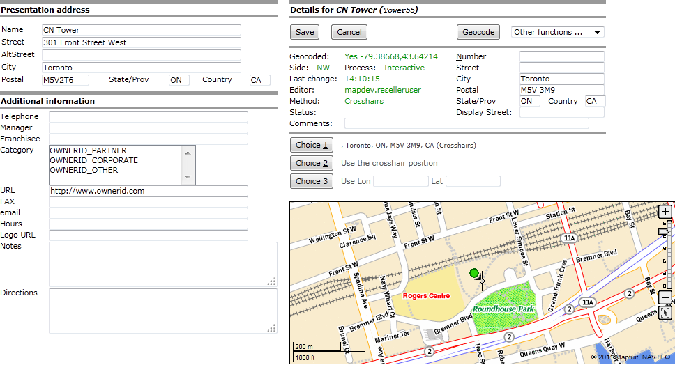
The Create POI screen looks like this:
On the Create POI screen, enter as much information as you can about the POI. You can use the following data fields to provide information:
Presentation Address
Name: Defines the name of the POI, for presentation purposes. The POI name does not have to be the same value as the POI ID that you specified when you clicked the Create button.Street: Defines the street of the POI, for presentation purposes.AltStreet: Defines an alternative street of the POI, for presentation purposes.City: Defines the city of the POI, for presentation purposes.Postal: Defines the zip/postal code of the POI, for presentation purposes.State/Prov: Defines the region code of the POI, for presentation purposes.Country: Defines the country code of the POI, for presentation purpose.
Additional Information
Telephone: Defines the telephone number of the POI.Manager: Defines the name of the manager of the POI.Franchisee: Defines the POI franchise name.Category: Defines the category of the POI.URL: Defines the website URL of the POI.Fax: Defines the fax number of the POI.email: Defines the email address of the POI.Hours: Defines the POI business hours.Logo URL: Defines the URL to the POI logo.Notes: Defines any custom notes or other important information about the POI.Warning Do not use abbreviations in this field because they may not be spoken as expected in applications such as NaviGo. For example, DR may be spoken as doctor instead of drive.
Directions: Defines any custom directions that can help people find the POI.
When you have finished entering the POI information, click the Save button. After you have saved the POI information, please read the Geocoding POIs section to learn how you can specify the actual location of your POI.
You can also perform a variety of Other Functions on the POI.
| Warning |
If you leave the screen without clicking Save, the POI will not be created. |
Editing POIs
If you know the full POI ID of the POI you want to edit, you can simply enter it in the POI ID field on the main screen and click Edit.
If the POI is found, the POI information is displayed on the edit screen.
If you do not know the full POI ID, please refer to the Searching for POIs section for more information. After performing a search, simply click the POI that you wish to edit.
After you have selected a POI to edit, the following edit screen is displayed:
Are you wondering what the different circle and square icons mean? Learn more about the POI Editor icons by referring to the Icon Legend. Similar to the behavior of the icons, the information that appears in the information panel is displayed in green font if it is unsaved.
When the edit screen is first displayed, the Save button is initially disabled (greyed out). The button is disabled because no changes to the POI have been made. After you add or change information on the screen, the button is enabled to allow you to save the information. When you have finished making your changes, click Save.
To edit the POI, simply modify any information on the screen, such as the Presentation address or Additional information.
Refer to the Geocoding POIs section to learn how you can modify the (geocode) location of the POI.
You can also perform a variety of Other Functions on the POI.
| Warning |
If you leave the edit screen without clicking Save, your changes will be lost. |
Geocoding POIs and Other Functions
While you are creating or editing a POI, you can perform a variety of operations, such as:
Geocode: refers to finding or specifying the lon/lat point where the POI is located.
Other Functions: allows you to perform operations such as deleting a POI, reverting to the saved version, removing geocode information, configuring a yard for the POI, sending feedback, or setting the protection mode.
Geocoding POIs
Geocoding a POI refers to finding the lon/lat point where the POI is located.
You can geocode POIs during the creation process, or you can edit a POI to add the geocode information at a later time.
When you are at the create/edit screen, you either have two or three choices for geocoding the address:
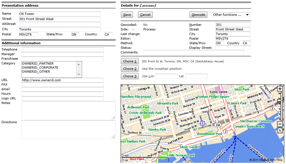
Choice 1: GeoAddress - Geocodes using the specified geocode POI address (on the right hand side of the screen) which is usually automatically copied from the presentation address.
Note: An explanation will sometimes appear after the Choice 1 address. For example, the following text may appears beside Choice 1 after geocoding: 301 Front St W, Toronto, ON, M5V, CA (GeoAddess; House). The (GeoAddress; House) part is new, and provides an indication of the search method that was used to locate the address. In this case, the address was found to the House level (which is the most accurate).
If ?? appears after the search method (e.g. (AltStreet; House near intersection ??)), we recommend that you double check the location that was found to ensure it is correct. The ?? portion of the explanation indicates that the search result is potentially substandard.
Choice 2: Crosshairs - Geocodes using the clicked crosshair location on the map.
Choice 3: Lon/Lat - Geocodes using the specified
LonandLatcoordinates.
| Warning |
Sometimes there are only two choices available ( |
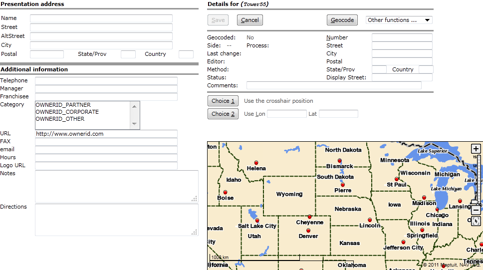
You can determine if a POI is geocoded by looking at the Geocode field.
If the POI has been geocoded, this field is set to Yes.
If the POI has not been geocoded, the field is set to No.
In the example below, the POI is saved but it is evident that there is no geocode information available because the Geocode field is set to No.
The POI information appears on the left, and the geocode information appears on the right hand side of the screen.
Updating the geocode information for a POI will not affect the presentation address or the additional information of the POI.
To geocode a POI, click the Geocode button.
POI Editor will attempt to geocode the specified geocode address.
The geocode address fields are (usually) automatically populated when you type the Presentation address of the POI.
You do, however, have the ability to specify a different geocode address for the POI.
After clicking the Geocode button, POI Editor attempts to find the lon/lat point of the address.
If the address is located, the address is displayed beside the Choice 1 geocode option button.
You will also see a blue square icon on the map at the location (blue square icons represent candidate locations).
If the location is correct, you can click the Choice 1 button to select the candidate address as the geocoded location.
At this point, the Method changes to GeoAddress and the map icon changes to either a green circle or green square icon, depending on whether or not the exact location (i.e. Side) is known.
After you save the location, the map icon becomes red.
Learn more about the POI Editor icons by referring to the Icon Legend
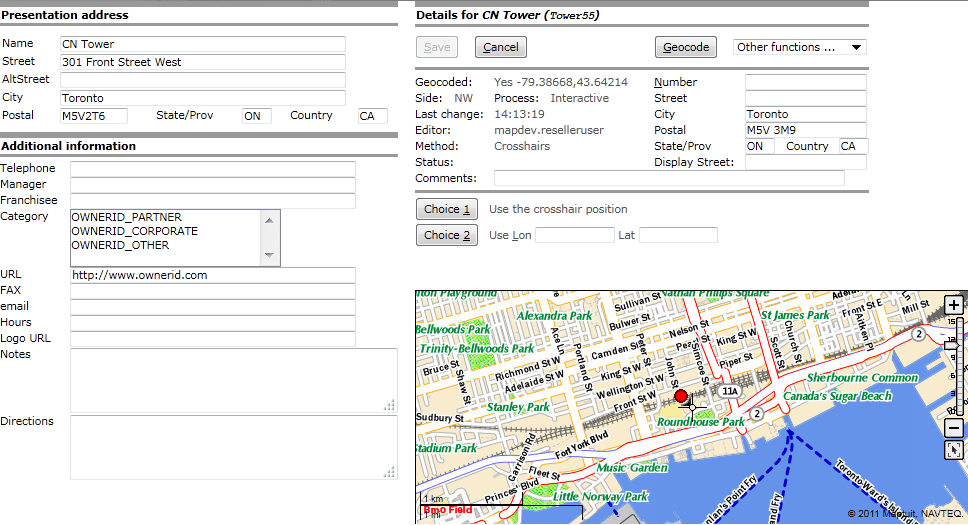
In our CN Tower example, the presentation address is not the actual location of the CN Tower. Therefore, Choice 1 is not the best option for this example. In this case, we need to correct the position of the POI.
In order to correct the position of the POI, you can click the map on the correct position, and then click Choice 2 to move the P OI indicator to that location. In the example below, the POI is displayed in the correct location.
In the figure above, the geocode information appears in green font because it has not yet been saved.
The Method field has been set to Crosshairs because Choice 2 has been selected for the geocode method.
If you already knew the lon/lat point of the POI, you do not have to click on the map and choose Choice 2.
Instead, you can simply specify the coordinates in the Lon and Lat fields, and then click Choice 3.
In this case, the Method changes to Lon/Lat.
Geocode Field Descriptions
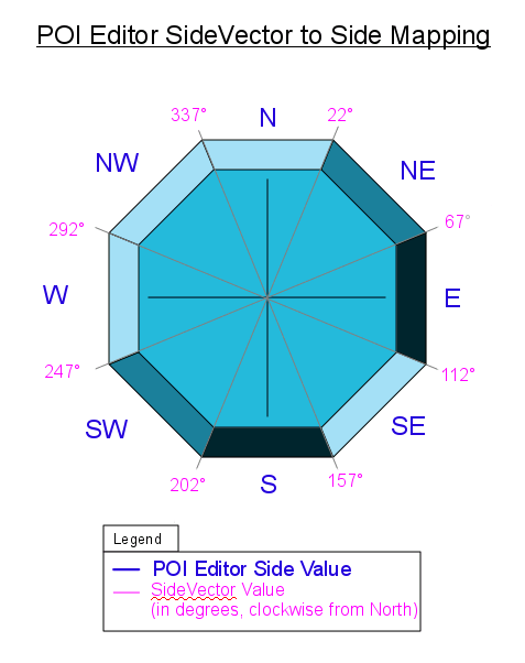
Geocoded: Indicates whether or not the POI is geocoded (YesorNo). If set toYes, the lon/lat point is displayed as well.Side: Provides information to determine what side of the road the POI is on, by providing the direction of the POI relative to the road network (e.g. N,NE,E,SE,S,SW,W,NW). For example, if the POI is located 20 degrees clockwise from north, then the Side value is set toNW. The diagram below outlines theSidevalues that are selected for variousSideVectorpossibilities:Process: Indicates the process that was used to last modify the POI (API,Interactive(POI Editor Web Application), orBatch)Last Change: Indicates the date the POI was last modified. This is set to a time if the POI was modified in the last 24 hours.Editor: Indicates the username of the last person who modified the POI.Method: Indicates the method that was used to geocode the POI (GeoAddress,Crosshairs, orLon/Lat)Status: Indicates the status of the POI.Comments: Indicates any comments that have been added to the POI.Number: Defines the house/building number of the POI geocode address.Street: Defines the street name of the POI geocode address.City: Defines the city of the POI geocode address.Postal: Defines the zip/postal code of the POI geocode address.State/Prov: Defines the region code of the POI geocode address.Country: Defines the country code of the POI geocode address.DisplayStreet: Defines the street name to use for display purposes.
POI Editor Icon Legend
Blue Square Icon with Number
The blue square icon indicates a candidate location. There can be multiple candidate locations displayed on a map. The icon displays a number so you can distinguish between multiple candidates.
Red Circle Icon (with arrow)
The red circle icon indicates that the POI location is saved. If the location information changes, the icon becomes green to indicate that it is no longer saved. The tip of the arrow points to the location on the road network that is used for the POI. The red circle is positioned so you can visually determine which side of the road the POI is located on. In this icon example, the actual POI location is slightly North West of the point (on the road network) that is stored for the POI.
Green Circle Icon (with arrow)
The green circle icon indicates that a location has been geocoded for the POI, but the location has not been saved. The tip of the arrow points to the location on the road network that is used for the POI. The green circle is positioned so you can visually determine which side of the road the POI is located on. In this icon example, the actual POI location is slightly North East of the point (on the road network) that is stored for the POI. After you save the POI, the green circle icon changes to a red circle icon.
Red Square Icon
The red square icon indicates that the POI location is saved. If the location changes, the icon becomes green. This icon means the same thing as the red circle icon, but the square shape (and absent arrow) indicates that the side of the road is unknown.
Green Square Icon
The green square icon indicates that a location has been geocoded for the POI, but the location has not been saved. This icon means the same thing as the green circle icon, but the square shape (and absent arrow) indicate that the side of the road is unknown.
Other Functions Menu
The Other functions... drop down allows you to perform a variety of operations:
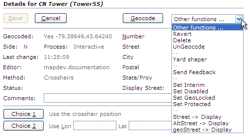
When you select a function from the Other functions... drop down list, the function is automatically performed immediately.
Some functions (e.g. Delete) require confirmation.
Here is the description of each operation that you can perform using the Other functions... drop down:
Revert: Allows you to undo the last operation. This operation does not work if you have already saved the POI. This operation cannot be used if you have deleted a POI.
Delete: Deletes the POI.
UnGeocode: Deletes the geocode information stored for the POI.
Yard Shaper: Allows you to associate a yard with a POI.
Send Feedback: Allows you to send feedback about the POI.
Set (or Clear) Interim: This option allows you to flag locations that should be revisited when data improves in the area. This flag should be set for locations for which it is currently necessary to position the location to an incorrect point because the actual location is not in the road network data. For instance, if a distribution center is located on Walmart Rd, but Walmart Rd is a newly constructed access road off US-421, and is not in our data, it might be appropriate to temporarily place the marker on US-412. In this case, the POI should be flagged as
Interim.If set, the POI presentation address is used to attempt to re-geocode the POI (when addresses are re-geocoded due to updates by the data provider). If this setting is enabled and no geocode address exists, the presentation address is used to re-geocode the POI (as if a new POI had been submitted). If this setting is NOT enabled, the existing geocode address is used to geocode the POI.
Set (or Clear) Disabled: If set, the POI becomes disabled and will not appear in POI searches. However, the POI can still be found and re-enabled when using the POI management services.
Set (or Clear) GeoLocked: This setting allows you to lock the geocode elements of the POI. After the POI is geoLocked, you can make changes to other POI elements without having to re-geocode the POI. For example, you may wish to set the geocoded location to a loading dock, which is different than the customer entrance of a store. This setting would allow you to change the presentation address or other elements, without re-geocoding the POI. If the POI is not GeoLocked, it would be re-geocoded using the presentation address, which would overwrite the location of the loading dock.
If set (enabled), the geocode elements of the POI become locked and will not be automatically re-geocoded. However, other POI elements (not related to geocoding) can be updated.
Set (or Clear) Protected: If set, all POI information (including geocode elements) are protected/locked and all updates to the POI are ignored.
Street -> Display: Sets the
Streetvalue as the displayed street for the POI.AltStreet -> Display: Sets the
AltStreetvalue as the displayed street for the POI.geoStreet -> Display: Sets the
geoStreetvalue as the displayed street for the POI.
Deleting POIs
You can delete a single POI, or perform a batch delete.
Deleting a Single POI
You can delete a single POI by navigating to the edit screen for the POI that you wish to delete.
On the edit screen, select Delete from the Other functions drop down menu.
POI Editor requires your confirmation prior to deleting a POI.
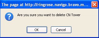
If you would like to delete the POI, click OK. Otherwise, click Cancel.
Deleting a Batch of POIs
| Warning |
If you click the Delete button when all search fields are blank, your search will match all POIs. If you confirm the deletion, your entire POI collection will be erased. |
You can delete a batch of APIs by completing the following steps:
On the main POI Editor page, complete the fields on the search form to match the POIs that you wish to delete. If, for some reason, you wish to delete all POIs, leave the search form blank.
Click the Delete button. After you click Delete, POI Editor pops up a new window that displays a list of all POIs that matched your search criteria.
Review the list of POIs that matched your search to ensure that you wish to delete the selected POIs.
The POIs are not deleted until after you click the Confirm Deletion button located in the new pop up window. If you wish to delete the POIs, click the Confirm Deletion button.
Yard Shaper
The Yard Shaper feature allows a fleet to associate a geofence (i.e. yard) with a POI. The yard information can then be captured and used for arrival, departure and association scenarios. For example, if a yard is defined for the POI, a nearby road will not be selected for the route starting point if the driver requests a route while located inside the yard. Instead, the routing services will use the defined yard exit point as the starting point for routes generated while located inside the yard boundaries.
Background: Prior to the introduction of the yard shaper feature, sometimes the wrong road would be selected as the route starting point when a driver requested a route while positioned inside the yard. For example, this issue would sometimes happen if a truck was located at the back of the yard near another road. When the route was requested, the road (outside of the yard) would be selected as the route starting point even though the truck was unable to access the road directly from the yard.
You can access yard shaper by selecting the Yard Shaper option from the Other functions... drop down list while creating or editing a POI.
The Yard Shaper screen automatically loads.
When you view a POI (with an associated yard) in POI editor, the yard is displayed on the map as a thin blue line. After you launch the yard shaper feature, the map zooms in and displays the yard shaded yard on the map.
Yard Shaper looks like this:
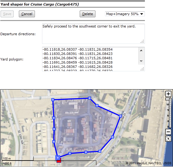
Yard Shaper consists of the following components/features:
Map Imagery Transparency Option:
Allows you to select the level of map imagery transparency. Map imagery is extremely helpful for identifying the actual boundaries of the yard.
Allows you to delete the yard currently associated with the POI.
Departure directions:
This text field allows you to specify textual directions about how to exit the yard. These directions are passed to NaviGo and handled as extra directions.
Yard polygon:
This text field defines the shape of the yard using lon,lat points (separated by spaces). This field is automatically populated when you click the map to draw yard points.
Tip: The
Yard polygonfield allows you to copy and paste the shape to use as a yard for a different POI. This is extremely useful if you have multiple POIs at the same location. Instead of redrawing the shape for each POI, you can copy and paste the Lon,Lat points.Warning: The
Yard polygonfield treats Lon,Lat points as absolute (not relative). Therefore, you cannot reuse (i.e. copy and paste) a shape for a POI at a different location.Interactive Map with yard drawing capabilities:
Provides you with the ability to create, modify, and erase yard shapes using an interactive map. Left-click the map to add a yard shape point, or right-click the map to view a menu of options.
Selecting the Map Imagery Transparency
Note: Imagery is currently only available for USA locations.
The map in yard shaper has the ability to display imagery data at various levels of transparency:
Map, no imagery: The standard map is displayed, without imagery.Map+Imagery 25%: The map is displayed with 25% imagery.Map+Imagery 50%: The map is displayed with 50% imagery.Map+Imagery 75%: The map is displayed with 75% imagery.Imagery only: The map is displayed with imagery only.Note: If you select this option, the map is displayed using 100% imagery. In this mode, road information is not displayed on the map.
Here are examples of each imagery option:
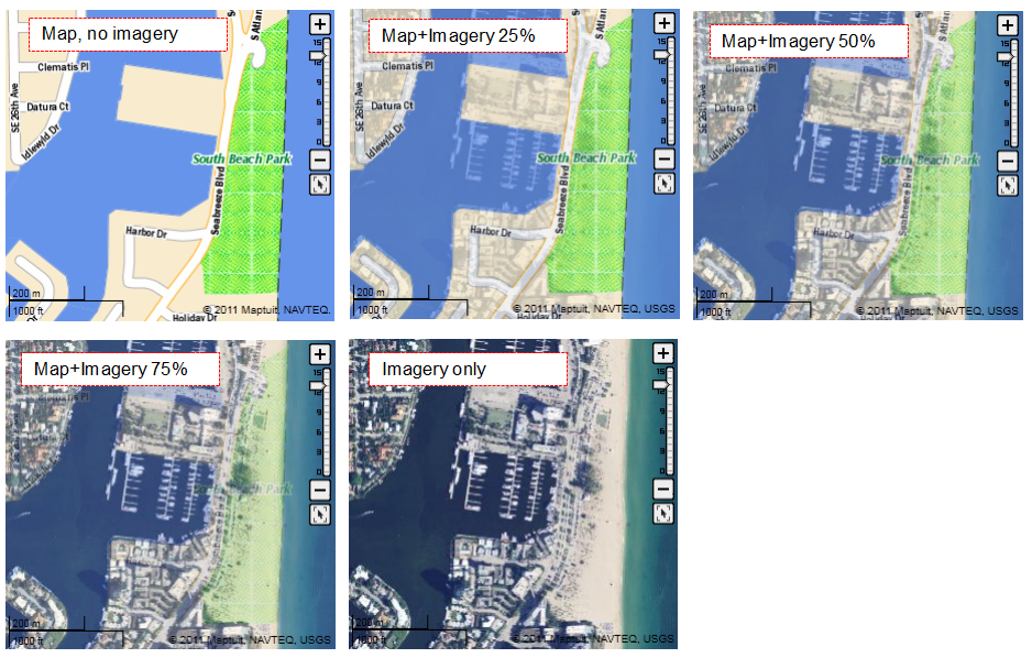
When you select a map imagery transparency option, the setting is preserved between sessions. Therefore, when you open a yard in a different POI, the same level of map imagery transparency is used for displaying the maps.
Deleting a Yard
To delete a yard that is associated with a POI, simply click the Delete button while you are in yard shaper mode. After you click the Delete button, the yard is automatically deleted and yard shaper mode is automatically closed.
Note: Be careful when deleting yards. There is no confirmation required when you click the Delete button.
Creating / Modifying Yards using Interactive Map
The Yard Shaper feature allows you to define a yard by drawing a polygon on the map. Map imagery is provided to help you define the boundaries of the yard as accurately as possible. For more information on map imagery, read more about selecting the map imagery transparency.
Creating a Yard
Currently, you can associate one yard with each POI. If the POI already has a yard associated with it, and you would like to replace the existing yard with a new yard, read more about deleting yards.
After you have launched yard shaper, you can begin drawing your yard by clicking the map at the yard exit point. A blue icon will appear on the map at the location that you clicked.
Important: Currently, a yard can have only one exit point. The first point of the polygon on the map is used for the yard exit point. The exit point is marked with a larger blue square icon than the other polygon points. However, you can only view this exit point when you are in yard shaper mode.
Proceed with drawing the polygon by clicking another location on the map to draw a line. Continue drawing the polygon by clicking on the map at the boundaries of the yard. While drawing a point, you can right-click the map to access a variety of options:
Drop point & continue: This action adds a point to the current mouse position.Tip: The same behavior can be achieved by left-clicking the location on the map.
End shape: This action attempts to end the shape at the current position. If the shape is incomplete, an error is reported.Cancel continue: This action stops the shape drawing process. To continue drawing the shape, simply left-click the last drawn point of the shape.
Completing the Shape
To complete the yard, you must first close the shape. If you hover over the first point while drawing the polygon, a tooltip is displayed that says Close polygon. Simply left-click while hovering directly over the first polygon point, and the polygon shape is completed. After the polygon shape is complete, the yard is shaded lightly in blue.
Note: If you attempt to end a shape that is not closed, the following error is displayed above the map:
Polygon is incomplete.
You can continue drawing an incomplete shape at any time by left-clicking the last shape.
After (or during) yard creation, you may wish to modify the yard using a variety of modification features.
Modifying a Yard
Yard Shaper offers various tooltips and extra features that can help you modify or improve a yard:
Sometimes you may want to add additional points to a polygon shape in order to improve the accuracy of the yard boundaries.
To add a point to the polygon, you can use one of the following methods:
Simply left-click the polygon line between the two points where you would like the new point added. A new point is immediately added, allowing you to move the new point to the desired location. Simply click the left mouse button at the appropriate location for the new point.
Right-click the line where you want the new point added, and then select Insert point from the options menu. The new point is added at the location on the line that you right-clicked. You can easily move the point to a new location.
When you hover on a point, a tooltip is displayed that says Move Point. You can begin moving the point by clicking the point with the left mouse button, or by right-clicking the point followed by selecting the Move point option from the menu. Then, move your mouse to the location where the next shaping point should be added. When you have stopped moving your mouse, a tooltip is displayed that says End Move. Click the left mouse button to finish moving the point.
While moving a point, you can right-click the map to access a variety of options:
Drop point & continue: This action adds a point to the current mouse position.Tip: The same behavior can be achieved by left-clicking the location on the map.
End shape: This action attempts to end the shape at the current position. If the shape is incomplete, an error is reported.Cancel continue: This action stops the shape drawing process. To continue drawing the shape, simply left-click the last drawn point of the shape.
You can delete a point by right-clicking the point to display the menu. Click the Delete point option from the menu. The point is deleted immediately. No confirmation is required.
Note: You can only delete a line if the polygon is complete (i.e. the yard is shaded in a light blue color). If you would like to delete a line that is part of an incomplete yard, you can do so by deleting a point instead.
You can delete a line of a complete polygon by right-clicking the line to display the menu. Click the Delete line option from the menu. The line is deleted immediately. No confirmation is required.
You can mark a point as the starting point. The polygon starting point is used for the Yard exit point.
To mark a point as the starting point (i.e. change the yard exit point), simply right-click the point that you want to become the new starting point. Next, click the Mark start point option from the menu.
The point is marked with the larger blue square icon, which means the point is the exit point for the yard.
Yard shaper maintains a full history of actions, allowing you to undo any number of yard shaper changes.
To undo the last change, simply right-click the map and select Undo from the menu.
Yard shaper maintains a full history of actions, allowing you to redo any number of undone changes.
To redo the last undone change, simply right-click the map and select Redo from the menu.
Note: The Redo option only appears in the menu if you have used the Undo option.
You can revert to the saved yard at any time. The saved yard means the yard that was defined the last time the yard shaper Save button was clicked.
To revert to the saved yard, simply right-click the map and select Revert from the menu.
Erasing an entire shape can be useful if you would like to start over. Erasing a shape is similar to deleting a shape, but the erase function will not exit yard shaper mode. Also, the erase feature will not permanently delete the yard. After erasing a yard, you can still Revert to the last saved yard.
To erase an entire shape, simply right-click the map and select the Erase entire shape option from the menu.
Yard shaper offers you an easy way to recenter and zoom and map so the entire shape is displayed. Simply right-click the map and select the Fit Entire Shape option from the menu.
Note: You may be unable to see the POI on the map after selecting the Fit Entire Shape option. This can happen if the POI location is located some distance from the yard. You can zoom out to view a larger area until you see the POI on the map.
Importing POIs
| Warning |
Any information that you import into POI Editor will overwrite any POI information that already exists. Therefore, if you have locations that have been manually geocoded, those will fall back to an ungeocoded state. We recommend that you first Export any locations that you do want overwritten, prior to importing additional customer locations. |
In many cases, we recommend that you first export any POI locations that you do want overwritten, prior to importing additional customer POI locations. Exporting first can be a way of preserving geocode data. Alternatively, you may import only a subset of column data. Re-importing a record for an existing code only overwrites the data columns in the update file. If the records are geocoded and you don't upload new address data or geo data (lat/long values), POI Editor will not change the geocodes. For example, for existing locations, you can upload customer notes or directions in an update file with just three columns (id,name,CustomDirections). Now, we'll explain what the import and export files look like.
Note: POI Yard information is currently not included in the export file.
In order to import batches of POI data, the data must be properly formatted in a file. The POI Editor accepts the following file formats:
Excel 95/97/2000 for Windows spreadsheets
Tab, Pipe, or Comma delimited text, in the ISO-8859-1 character set
Regardless of the file format, the first row of your import file must be a header row denoting the order of the data fields in subsequent rows. For Excel files, each sheet in the file is read in order (only the first sheet should have a header row). The remaining sheets must be in the same format.
The following table outlines the fields that MUST exist in your POI data import file:
Table 11. Required Fields
| Field Name | Description | Maximum length |
|---|---|---|
| id | Your unique identifier for the POI | 32 |
| name | The name of this POI (REQUIRED) | 128 |
The following table outlines the fields that are OPTIONAL in your POI data import file:
Table 12. Optional Fields
| Field Name | Description | Maximum length |
|---|---|---|
| street | Street address | 256 |
| altstreet | Alternative street address | 256 |
| city | City/Town | 256 |
| region | 2 or 3 letter code for the state, province, or region | 3 |
| country | ISO standard country code | 2 |
| postal | ZIP or other postal code | 12 |
| longitude | Pre-geocoded longitude | Must be a valid longitude coordinate. |
| latitude | Pre-geocoded latitude | Must be a valid latitude coordinate. |
| scalelimit | Highest scale at which this POI is drawn on a map, default 20 | value up to 5000 |
| telephone | Phone number | 256 |
| telephonetwo | Alternate phone number | 256 |
| fax | Fax number | 256 |
| hours | Operating / Store Hours | 256 |
E-Mail Address | 256 | |
| url | URL to POI website / details | 65536 |
| logourl | URL to logo image | 65536 |
| keywords | Whitespace-separated list of keywords | 65536 (total) |
| notes | General notes about this POI | 65536 |
| class | Class value for this POI, for ActiveLayers integration | value from -32767 to 32767 |
| description | Description of this POI | 65536 |
| priority | The priority level. | integer |
| directions | Custom direction text | 65536 |
| displaystreet | Street address to display instead of geocoded address | 256 |
| Custom Fields | Custom fields may be specified by using a column header in the form "Custom_[keyname]", where [keyname] is the name of the custom field being stored. | 65536 (for all custom data, including keys and values) |
Below is an example of a properly formatted input file. The file contains the 2 required fields (id,name) as well as 5 optional fields (street,city,region,country,postal).
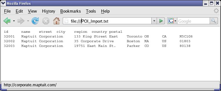
After you have finished creating your import file, click Import on the main screen of the POI Editor to begin the import process.
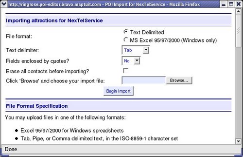
On the import screen, you must specify the format of your import file, and then click Browse to locate the file that contains the POI data that you wish to import. Click Begin Import to begin the process of importing your POI data.
| Warning |
The connection must remain open while the data is being imported. Therefore, it is recommended that you do not import extremely large batches of data. It is recommended that you import data in smaller batches, or use the API to import your data. You can also contact your customer support representative for assistance. |
The POI Editor reads your input file, and notifies you if there is an error with the format of your file. If your input file is properly formatted and the import is successful, the following screen is displayed:
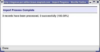
Exporting POIs
You can export your POI data to a tab-separated .txt file. You can either export all POI data, or you can specify search criteria to export the data that you need.
Note: POI Yard information is currently not included in the export file.
To export all POI data, leave the search fields blank and click Export. To export only a portion of the POI data, specify search criteria in the fields and click Export.
The POI Editor searches for the POI entries that meet your criteria, and creates a tab-separated .txt file that contains your data. The screen displays the number of records that were found, and provides a DOWNLOAD EXPORT RESULTS link for you to download your export results.
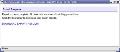
To download the file, click the DOWNLOAD EXPORT RESULTS link and save the file. The exported data is contained in a .txt file. An example is shown in the screenshot below:
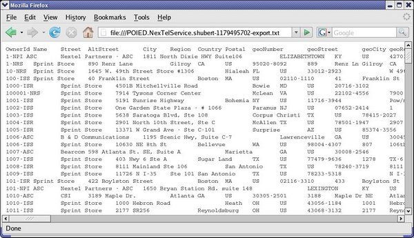
NaviGo RoadManager
Overview
Road Manager is a NaviGo Portal application that allows you to manage road modifiers for your fleet. Road modifiers are used to record information for a particular stretch of road. For example, you can mark an area of a road as a construction area or residential area. These road modifiers can then be used to produce more efficient routes.
Warnings and Tips
Handling Crossovers
NAVTEQ data does not include private roads and crossovers.
The following workarounds are currently available for dealing with crossovers that are not in the NAVTEQ data:
Add a note in the Directions field for the POI. The note can provide information to drivers about where and which way to turn (e.g. from the East, turn left. From the west, turn right.)
Place the POI lon/lat point 'on' the crossover and then use a small radius so the POI area reaches both roads. Of course, the directions would only navigate the driver to the lon/lat point 'on' the crossover (instead of directly to the POI).
Note: Contact customer support for more information or assistance.
Searching for Modifiers
When RoadManager initially loads, there are no modifiers displayed by default.
There are always 3 buttons displayed on the Search page. These buttons provide you with the ability to perform the following operations:
The Search button allows you to perform basic searches, and searches using various Additional Options.
The New Modifier button allows you to create a new modifier.
The Reset Form button allows you restore the search criteria to the defaults.
After you have performed a search, you can View and Sort Modifiers on the screen. You can also click modifier name links to View or Edit Modifier Details.
As a shortcut, you can search for all modifiers by simply clicking the Search button prior to modifying any search fields. If you have modified search fields, simply click the Reset Form button to clear the form, and then click Search to view all modifiers. After searching for all modifiers, it may be useful to Sort Modifiers on the screen so you can more easily find the modifier you are seeking.
Or, you can locate modifiers more quickly and efficiently by using the various search fields available on the search form. Road Manager offers a wide variety of search options so you can find modifiers more easily. Road Manager only returns search results if the modifier matches all of the specified search criteria.
The most commonly used search fields are displayed at all times on the search form. Additional search options are available by clicking the Additional Options link located at the bottom of the search form.
The Road Manager search form looks like this:
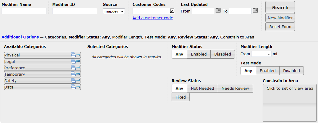
You can show or hide the additional options at any time by clicking the Additional Options link.
For your convenience, a summary of the additional options are displayed so you can see what options are set even when the additional options panel is hidden.
When a particular option is displayed in bold font, it means that the search option has been set to a value (e.g. Modifier Status: Any).
As stated previously, Road Manager only returns search results if the modifier matches all of the specified search criteria. You can use the following search fields to narrow down your search results:
Modifier Name: If specified, modifiers are only returned if the modifier name partially matches the specified text. Searches by modifier name are not case sensitive. For example, searching for brokenbridge will match a modifier with the name BrokenBridgeOnKingStreet.After typing at least 3 characters into the Modifier Name field, a list of all matching modifiers (from the current fleet) are displayed to help you find the modifier you are seeking. This type ahead feature lists all matching modifiers, and will not filter out modifiers based on other criteria specified in the search form.
Modifier ID: If specified, modifiers are only returned if the modifier ID starts with matches the specified text. For example, searching for 123 will match a modifier with ID 12345 but will not match a modifier with ID 91234.Source: This filter allows you to select the modifier source. You can only search for modifiers from one source at a time.Customer Codes: If specified, the search results will only return modifiers that contain all of the customer code locations specified on the search form (even if the Modifier contains additional Customer Codes that are not listed on the search form). Customer codes must partially match the specified text. The search is not case sensitive. For example, searching for FF will match the customer code @office.You can add additional customer codes by clicking the Add a customer code link. To remove a customer code, click the X icon located on the right hand side of the customer code field.
Last Updated: TheFromandTofields allow you to specify a start date and an end date by clicking the calendar and choosing a date. These filters allow you to limit the search results to modifiers that were last updated between two dates, before a particular date, or after a particular date. If specified, the search results will only contain modifiers that were last updated during the specified date range. If both aFromandTodate are specified, theFromdate must be older than theTodate.Categories: This filter allows you to limit search results to modifiers that have one of the selected categories. For example, if only one category is selected, the search results will only contain modifiers that are set to that particular category. If many categories are selected, the search results will contain modifiers with only those selected categories.Simply click on a category group (e.g. Physical) under the
Available Categoriesheading to view the individual categories. You can add an entire category group or individual categories by clicking on the right-pointing arrow icon. You can remove selected categories by clicking on the left-pointing arrow icon under theSelected Categoriesheading.Modifier Status: This filter allows you to limit search results to one of the following modifier status settings:Any: This option does not filter out any modifiers.Enabled: This option filters out modifiers with a disabled status. The search results will only include modifiers with an enabled status.Disabled: This option filters out modifiers with an enabled status. The search results will only include modifiers with a disabled status.
Modifier Length: This filter allows you to limit search results to one of the following length ranges:1ft to ¼miles¼ to ½miles½ to 1miles1 to 2miles2 to 6miles> 6miles
Note: The length options are displayed in KM instead of miles if your fleet is configured to use kilometer units.
Test ModeStatus: This filter allows you to limit search results to one of the following test mode status settings:Any: This option does not filter out any modifiers.Enabled: This option filters out modifiers with a disabled test mode status. Search results will only include modifiers with an enabled test mode status.Disabled: This option filters out modifiers with an enabled test mode status. Search results will only include modifiers with a disabled test mode status.
Review Status: This filter allows you to limit search results to one of the following review status settings:Any: This option does not filter out any modifiers.Not Needed: Search results will only include modifiers with a not needed review status.Needs Review: Search results will only include modifiers with a needs review review status.Fixed: Search results will only include modifiers with a fixed review status.
Constrain to Area: If a map constraint area is set, search results will only contain modifiers that are at least partially located within the specified area.To set a map constraint area, first click the gray box on the search form to display the map selection area. Then, zoom the map into the area that you wish to select, and then click the Select Area button. You can now click and drag your mouse on the map to draw a rectangle. After you release the mouse button, a gray rectangle remains displayed on the map. This gray rectangle identifies the search constraint area. To accept the selected area, click the Accept button. Or, click the Select Area button again to re-draw the constraint area. If you wish to remove the map constraint area at any time, click the Clear button and then click Accept to save the map without a constraining area.
After you have set your search criteria, click the Search button to view your results. Read more about Viewing and Sorting Search Results.
Viewing and Sorting Road Modifier Search Results
After you have performed a search, the road modifier results are displayed on the Search page:
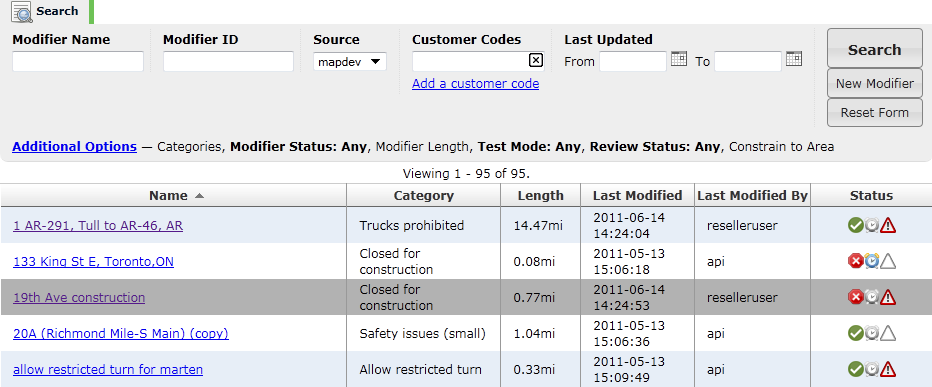
Tip: Modifiers that have been viewed are displayed with purple hyperlinks instead of blue hyperlinks. The last viewed modifier is displayed with a grey colored background.
The modifier search results are displayed on the screen in a table format. Each modifier is displayed as a row, and the columns provide the following information about each modifier:
Name: Indicates the name of the modifier. Simply click the name to View or Edit the Modifier Details.Category: Indicates the category of the modifier (e.g. Closed for Construction).Length: Indicates the length of the modifier (e.g. 0.186mi).Last Modified: Indicates the date and time that the modifier was last modified.Last Modified By: Indicates the username of the person who last modified the modifier, or displaysapiif the modifier was last modifies using an API service.Status: Indicates status information using a variety of icons (see below).The following Modifier Status icons indicate whether the modifier is enabled or disabled:
The green checkmark icon indicates that the modifier is enabled.
The red X icon indicates that the modifier is disabled.
The following Date Range Status icons indicate whether a date range is set for the modifier:
The gray clock icon indicates that a date range is not set for the modifier.
The blue and yellow clock icon indicates that a date range is set for the modifier.
The following Needs Review Status icons indicate whether the modifier requires review:
The empty triangle icon indicates that review is not needed, or the modifier has been fixed.
The red triangle icon (with an exclamation mark) indicates that the modifier needs review.
Sorting Results
Sometimes your search may return a large number of results, making it difficult to find the road modifier that you are trying to find. Sorting the results will help you locate the modifier that you are trying to find.
To sort the results, simply click the column header of the criteria that you wish to sort by. You can click the same icon again to sort the results in reverse order.
You can sort the results by any column except the Status column.
You can, however, search for modifiers using the Additional Options in order to find modifiers that have a particular modifier status, test mode status, or needs review status.
Viewing Multiple Pages of Results
Road manager separates the road modifier results into multiple pages, depending on the number of results. You can select a different page by clicking on the page number at the top of the screen.
Note: By default, a maximum of 100 road modifiers are displayed per page. Contact your contact support representative if you would like to display a different number of road modifiers on each page.
Creating New Modifiers
Note: Prior to creating a new modifier, it is a good idea to perform a search to ensure that a duplicate modifier does not already exist.
You can access the New Modifier page by clicking the New Modifier link located on the Search tab:
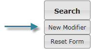
The New Modifier page looks like this:
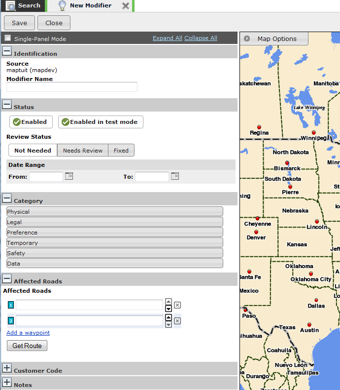
To create a new modifier, specify all of the modifier details and then click the Save button. To cancel the new modifier, click the Close button.
Information about the modifier details panels are outlined below.
New Modifier Page Overview
When the New Modifier page appears, information panels appear on the left hand side, and a map is displayed on the right hand side of the screen. For more information about the map capabilities, refer to the Map Options section.
Each information panel contains required and optional road modifier information fields. The following panels contain required fields and are automatically open when you view the screen:
IdentificationStatusCategoryAffected Roads
You can view or hide the panels by clicking on the + and - icons displayed on the left hand side of the panel titles.
To view all panels, click the Expand All link.
To hide all panels, click the Collapse All link.
You can also place a checkmark in the Single-Panel Mode option if you prefer to view only one panel at a time.
Identification Panel
Source: This field is completed for you automatically and cannot be changed. While viewing modifiers on a map, you can display or hide modifiers from different sources (e.g. NavTeq, Maptuit, yourSource).Modifier Name: Type the new modifier name into theModifier Namefield.Note: This field is required. A modifier name must be specified before you can save a modifier.
Status Panel
Modifier Status
Indicates whether a modifier is enabled or disabled. Disabled modifiers will have no impact on routing.
Click the button to toggle between
EnabledandDisabledfor the Modifier Status.Note: If at least one of the
FromorTodates are set, the '(via date range)' text is displayed beside the modifier status control. When this happens, the modifier status cannot be changed manually.Test Mode Status
Indicates whether a modifier is enabled or disabled in test mode. You can then experiment with routes in Route Generator using test mode modifiers (without impacting routing in production).
Click the button to toggle between
Enabled in test modeandDisabled in test modefor the Test Mode Status.Note: The test mode feature/option is not available by default. Therefore, you may not see this option on your screen. To enable this feature, contact your customer support representative.
Review Status
The
Review Statusfield is an informational field that provides information about whether or not a modifier requires review.The following status options can be assigned to a modifier:
Not Needed: Indicates that the modifier does not require review.Needs Review: Indicates that the modifier requires review.Fixed: Generally indicates that a modifier was reviewed and then fixed.
Date Range
The date range feature allows you to configure Road Manager to automatically enable and/or disable a modifier based on the specified date range. If both the
FromandTodates are set, the modifier is automatically enabled on theFromdate and then disabled on theTodate. The automatic status changes will occur prior to start of business on the specified day.From: Indicates that the modifier should become enabled automatically on the specified date. If only theFromdate is set, the modifier is automatically enabled on theFromdate and remains enabled.To: Indicates that the modifier should become disabled automatically on the specified date. If only theTodate is set, the modifier is automatically disabled on theTodate and remains disabled.Would you like to be reminded via email?: Indicates whether or not you wish to receive an email reminder whenever a modifier is automatically enabled or disabled. To receive an email reminder, simply selectYesand then type your email address into the space provided. You can specify a single email address, or specify multiple email addresses by separating the addresses with a comma. Email reminders are sent immediately after the status of the modifier is automatically changed by Road Manager.Note: This option only appears in the panel if you have specified a date for at least one of the
FromorTofields.
Category Panel
Note: This field is required. A category must be selected before you can save a modifier.
To select a category, simply click the category group to expand the list of categories. Then, choose a category by clicking the appropriate option.
For more information about road modifier categories, refer to the Modifier Categories section.
Affected Roads Panel
Note: This field is required. You must generate a route successfully before you can save a modifier.
To specify the affected roads, perform the following steps:
Specify a start address using one of the following methods:
Type an address into the first field.
Refer to the Finding Locations section for more information about acceptable inputs for specifying an address.
Note: When you use a POI to specify the location of a road modifier, you must put an @ symbol ahead of the POI ID if the ID begins with one or more spaces.
Click a location on the map and select the Route starts here link.
Specify an end address using one of the following methods:
Type an address into the second field.
Refer to the Finding Locations section for more information about acceptable inputs for specifying an address.
Click a location on the map and select the Route ends here link.
[Optional] Add a way point using one of the following methods:
Click the Add a Way Point link and then type the address into the new field
Click a location on the map and select the Add waypoint here link.
Click the Get Route button to get the route.
Finally, review the generated route to ensure that the affected roads are correct. If the affected roads are not correct, you can change the shape of the route by clicking a location on the map and selecting the Add way point here link. After adding a way point, you must click the Get Route button to generate the route with the new way point.
You can change the order of points by using the up and down arrow icons located beside each point. You can remove points by clicking the X icon located beside each point.
Important: Always click the Get Route button and review the affected roads route after making any changes to the routing points.
A route must be generated successfully in order to save a modifier.
Affected Road Warnings
Road Manager provides warnings to help you create more efficient road modifiers.
Long Modifier Warning
If you attempt to create a road modifier that is longer than 10km (6.2 mi), Road Manager will display a warning message.
Note: Please contact your customer support representative to configure a different distance value for this feature.
Overlapping Modifier Warning
If you attempt to create a road modifier that overlaps with an existing modifier, Road Manager will display a warning message. This feature can help you prevent the creation of duplicate modifiers.
Customer Code Panel
The Customer Code panel allows you to associate POIs with a road modifier.
Note: If you select a
Preferred approach to locationpreference for a road modifier, you must associate the modifier with a POI.
The customer codes must be specified in the appropriate customer code format (e.g. @maptuit).
| Warning |
If you specify a customer code, the road modifier will only apply to routes that travel to that customer/POI location. |
You can add additional customer codes by clicking the Add another location link. To delete a location, simply click the X icon located beside the location that you wish to delete.
If you associate a customer code (POI ID) with a modifier, the customer location(s) are marked on the map with a yellow star icon. You can easily view the location of customer codes by clicking the Map link located to the right hand side of each customer code in the Customer Code panel. You can also view a list of nearby customer locations by clicking on the map.
Notes Panel
Modifier Notes: Indicates any additional information about the modifier.System Notes: This field contains system messages associated with the modifier. This field is intended to be used for notes generated during modifier migration.Note: This field cannot be edited.
Viewing and Editing Modifier Details
You can access the modifier details page (i.e. [modifier name] page) by clicking on the modifier name on the main screen (after viewing all or performing a search).
The modifier details page looks like this:
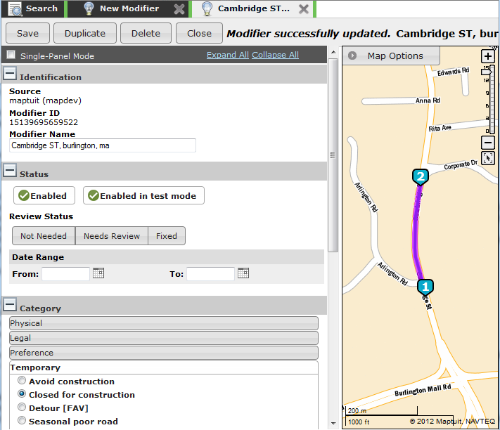
To edit an existing modifier, perform a search and then click the modifier name on the Search page. When the Modifier Details page appears, you can make modifications to the information in the fields.
Modifier Details Page Overview
The Modifier Details page looks very similar to the New Modifier page, except that the fields display the modifier information.
Additionally, a History panel provides you with information about previously saved information about the modifier.
Also, you can see the affected roads displayed on the map displayed on the right hand side of the screen.
For more information about the map capabilities, refer to the Map Options section.
Each information panel contains required and optional road modifier information fields. The following panels contain required fields and are automatically open when you view the screen:
IdentificationStatusCategoryAffected Roads
You can view or hide the panels by clicking on the + and - icons displayed on the left hand side of the panel titles.
To view all panels, click the Expand All link.
To hide all panels, click the Collapse All link.
You can also place a checkmark in the Single-Panel Mode option if you prefer to view only one panel at a time.
Identification Panel
Source: This field is completed for you automatically and cannot be changed. While viewing modifiers on a map, you can display or hide modifiers from different sources (e.g. NavTeq, Maptuit, yourSource).Modifier Name: Type the new modifier name into theModifier Namefield.Note: This field is required. A modifier name must be specified before you can save a modifier.
Status Panel
Modifier Status
Indicates whether a modifier is enabled or disabled. Disabled modifiers will have no impact on routing.
Click the button to toggle between
EnabledandDisabledfor the Modifier Status.Note: If at least one of the
FromorTodates are set, the '(via date range)' text is displayed beside the modifier status control. When this happens, the modifier status cannot be changed manually.Test Mode Status
Indicates whether a modifier is enabled or disabled in test mode. You can then experiment with routes in Route Generator using test mode modifiers (without impacting routing in production).
Click the button to toggle between
Enabled in test modeandDisabled in test modefor the Test Mode Status.Note: The test mode feature/option is not available by default. Therefore, you may not see this option on your screen. To enable this feature, contact your customer support representative.
Review Status
The
Review Statusfield is an informational field that provides information about whether or not a modifier requires review.The following status options can be assigned to a modifier:
Not Needed: Indicates that the modifier does not require review.Needs Review: Indicates that the modifier requires review.Fixed: Generally indicates that a modifier was reviewed and then fixed.
Date Range
The date range feature allows you to configure Road Manager to automatically enable and/or disable a modifier based on the specified date range. If both the
FromandTodates are set, the modifier is automatically enabled on theFromdate and then disabled on theTodate. The automatic status changes will occur prior to start of business on the specified day.From: Indicates that the modifier should become enabled automatically on the specified date. If only theFromdate is set, the modifier is automatically enabled on theFromdate and remains enabled.To: Indicates that the modifier should become disabled automatically on the specified date. If only theTodate is set, the modifier is automatically disabled on theTodate and remains disabled.Would you like to be reminded via email?: Indicates whether or not you wish to receive an email reminder whenever a modifier is automatically enabled or disabled. To receive an email reminder, simply selectYesand then type your email address into the space provided. You can specify a single email address, or specify multiple email addresses by separating the addresses with a comma. Email reminders are sent immediately after the status of the modifier is automatically changed by Road Manager.Note: This option only appears in the panel if you have specified a date for at least one of the
FromorTofields.
Category Panel
Note: This field is required. A category must be selected before you can save a modifier.
To select a category, simply click the category group to expand the list of categories. Then, choose a category by clicking the appropriate option.
For more information about road modifier categories, refer to the Modifier Categories section.
Affected Roads Panel
Note: This field is required. You must generate a route successfully before you can save a modifier.
To specify the affected roads, perform the following steps:
Specify a start address using one of the following methods:
Type an address into the first field.
Refer to the Finding Locations section for more information about acceptable inputs for specifying an address.
Note: When you use a POI to specify the location of a road modifier, you must put an @ symbol ahead of the POI ID if the ID begins with one or more spaces.
Click a location on the map and select the Route starts here link.
Specify an end address using one of the following methods:
Type an address into the second field.
Refer to the Finding Locations section for more information about acceptable inputs for specifying an address.
Click a location on the map and select the Route ends here link.
[Optional] Add a way point using one of the following methods:
Click the Add a Way Point link and then type the address into the new field
Click a location on the map and select the Add waypoint here link.
Click the Get Route button to get the route.
Finally, review the generated route to ensure that the affected roads are correct. If the affected roads are not correct, you can change the shape of the route by clicking a location on the map and selecting the Add way point here link. After adding a way point, you must click the Get Route button to generate the route with the new way point.
You can change the order of points by using the up and down arrow icons located beside each point. You can remove points by clicking the X icon located beside each point.
Important: Always click the Get Route button and review the affected roads route after making any changes to the routing points.
A route must be generated successfully in order to save a modifier.
Affected Road Warnings
Road Manager provides warnings to help you create more efficient road modifiers.
Long Modifier Warning
If you attempt to create a road modifier that is longer than 10km (6.2 mi), Road Manager will display a warning message.
Note: Please contact your customer support representative to configure a different distance value for this feature.
Overlapping Modifier Warning
If you attempt to create a road modifier that overlaps with an existing modifier, Road Manager will display a warning message. This feature can help you prevent the creation of duplicate modifiers.
Customer Code Panel
The Customer Code panel allows you to associate POIs with a road modifier.
Note: If you select a
Preferred approach to locationpreference for a road modifier, you must associate the modifier with a POI.
The customer codes must be specified in the appropriate customer code format (e.g. @maptuit).
| Warning |
If you specify a customer code, the road modifier will only apply to routes that travel to that customer/POI location. |
You can add additional customer codes by clicking the Add another location link. To delete a location, simply click the X icon located beside the location that you wish to delete.
If you associate a customer code (POI ID) with a modifier, the customer location(s) are marked on the map with a yellow star icon. You can easily view the location of customer codes by clicking the Map link located to the right hand side of each customer code in the Customer Code panel. You can also view a list of nearby customer locations by clicking on the map.
Notes Panel
Modifier Notes: Indicates any additional information about the modifier.System Notes: This field contains system messages associated with the modifier. This field is intended to be used for notes generated during modifier migration.Note: This field cannot be edited.
History Panel
The history panel provides you with the modifier creation date and the date it was last modified. You can also view the differences between the current modifier information and a historical version.
To view the differences between the current modifier and a historical version, simply click a record in the list. Each record displays the date and time of the change, as well as the username of the person who made the change. After you have selected a record, click the View History button. The modifier history is then displayed in the current tab, with differences from the current version displayed highlighted in the color orange.
While you are viewing the history record of a modifier, the following buttons are inaccessible/disabled:
Duplicate: You cannot duplicate a modifier while viewing a history record. If you would like to duplicate the modifier, click the Current Modifier button to revert to the current data for the modifier.
Delete: You cannot delete a modifier while viewing a history record. If you would like to delete the modifier, click the Current Modifier button to revert to the current data for the modifier.
You can revert back to the currently saved modifier at any time by clicking the Current Modifier button.
Deleting an Existing Modifier
| Warning |
After you delete a modifier, it cannot be restored. Instead of deleting the modifier, you may wish to consider disabling it instead. |
To delete a modifier, perform a search for the modifier and then click the modifier name on the Search page. When the Modifier Details page appears, review the modifier information to ensure it is the modifier that you wish to delete. If you are sure you wish to delete the modifier, click the Delete button.
After you click the Delete button, the following dialog appears to confirm the deletion:
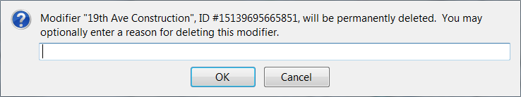
You may optionally enter a reason for deleting the modifier in the space provided. To confirm the deletion of the modifier, click the OK button. Or, to cancel the deletion, click the Cancel button.
Note: You cannot delete a modifier unless it has been saved. Therefore if you are creating a new modifier and wish to delete it, simply click the Cancel button.
Duplicating an Existing Modifier
To duplicate a modifier, perform a search for the modifier and then click the modifier name on the Search page. When the Modifier Details page appears, review the modifier information to ensure it is the modifier that you wish to copy. If you are sure you wish to make a copy of the modifier, click the Duplicate button.
After you click the Duplicate button, the following dialog appears:
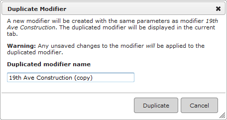
By default, Road Manager appends (copy) to the end of the existing modifier name. You can change the name of the new modifier by editing the text in the space provided. To confirm the duplication of the modifier, click the Duplicate button. Or, to cancel the duplication, click the Cancel button.
Note: The new modifier is created using the information displayed on the screen. Therefore, any unsaved changes to the modifier are applied to the duplicated modifier. After duplicating a modifier, the new (i.e. duplicated) modifier is displayed in the tab (not the old/existing modifier.
Map Options
The Map Options Panel allows you to control the elements and information that is displayed on the map.
The map options panel is located in the top left hand corner of the map. Simply click the Map Options button to open or close the Map Options Panel.
The Map Options Panel looks like this:
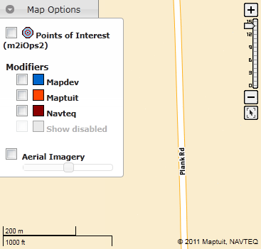
You can enable/disable the following map options:
Points of Interest: Displays your fleet's points of interest on the map. These do not include NAVTEQ POIs or fuel POIs. Points of interest can be viewed on the map at scale level 10 and higher.Fleet Modifiers (e.g.
Mapdev): Displays your fleet's modifiers on the map. Fleet modifiers can be viewed on the map at scale levels 6 and higher.Maptuit: Displays Maptuit global modifiers on the map. Maptuit's modifiers are drawn from our data sources, including feedback from drivers. Maptuit global modifiers can be viewed at map scale levels 11 and above.Navteq: Displays NAVTEQ modifiers on the map. Navteq modifiers can be viewed on the map at scale levels 11 and above.Show disabled: Displays disabled modifiers on the map. Disabled modifiers can be viewed on the map at scale levels 6 and above.Note: The
Show disabledoption is only accessible if you have selected at least one modifier source (e.g. your fleet, Maptuit, or Navteq). WhenShow disabledis selected, disabled modifiers are only displayed on the map for the selected source(s) (e.g. your fleet, Maptuit, or Navteq).Displays the map using aerial imagery. When this option is enabled, you can use the slide bar to control the degree of aerial imagery transparency. Aerial imagery can be displayed at all map scale levels but is only available for maps of the USA and some portions of Canada.
Note: To enhance map performance, some map options are only available at a minimum scale level. If you are zoomed out too far for a particular map option, the option is grayed out and no longer available. After you zoom in to a certain level, the option will become active again.
Finding Locations
You can search for your start location, stop locations, or destination location using a variety of inputs.
OneBox understands a wide variety of inputs so you can quickly and easily specify a location. Here are some well-formed common input examples:
35 Corporate Drive, Burlington, MA: Comma-separated address providing street, city, and region information
@maptuit: Searches for a POI (triggered by @ symbol) with a maptuit ID.
fuel: Searches for fuel stations ahead (if a route is available), or nearby
-79.37295,43.65023: Searches for the specified coordinates.
sushi near toronto, on: Searches for sushi keyword near Toronto, On. Refer to the OneBox Documentation for a full list of available keywords.
For a complete list of acceptable inputs, and additional information about OneBox, see the OneBox Documentation.
Modifier Category Descriptions
| Warning |
Multiple overlapping modifiers will have a cumulative effect. |
Physical Restrictions
Height restriction:The maximum height allowance for a truck to travel on a road, bridge, through a tunnel, or other. A standard truck has a height of 13'6" and is legal on most truck designated routes. However, every state has their own maximum height restriction for trucks.
Choosing this category will result in routes that avoid the part of the road segment where the height restriction is located.
This category requires that you specify the
Maximum vehicle heightmeasured infeet.Weight restriction:The maximum weight allowance for a truck to travel on a road, through a tunnel, or on a bridge. Weight limits are the legal limits provided by the Federal laws in the US. The maximum weight for a truck is 80,000 lbs or 40 tons.
Choosing this category will cause the affected road segments to not be used for routing. Alternate road segments are used for route generation.
This category requires that you specify the
Maximum gross vehicle weightmeasured inpounds.Turn restricted:The length limit for trucks to make a turn.
This road modifier category will prevent routes from travelling along all of the road segments identified using this road modifier from start to finish. This road modifier is generally used to restrict a turn. Routes may still use the affected road segment(s) as long as the route does not travel from the start to the end of the road modifier along the affected roads. For example, you can use this category to restrict a left hand turn without affecting right hand turns at the intersection.
This category requires that you specify the
Maximum overall vehicle lengthmeasured infeet. The modifier is then only applied to vehicles longer than the specified length.This category requires that the Affected Roads contains between 2 and 8 road links.
Per axle weight restriction:The weight limit for each size of truck. A single axle: 20,000 ; double axle: 34,000 ; triple axle: 45,000 ; 4 axle: 66,000 ; 5 axle: 80,000
Choosing this category will cause the affected road segments to not be used for routing. Alternate road segments are used for route generation.
This category requires that you specify the
Maximum gross vehicle weight per axlemeasured inpounds.Length restriction:The length limit for a truck to travel on a road, bridge or tunnel. The limit for a standard truck is 53 feet. However, every state has their own length limits. Trailer lengths up to 59.5 feet are legal in some states.
Choosing this category will cause the affected road segments to not be used for routing. Alternate road segments are used for route generation.
This category requires that you specify the
Maximum overall vehicle lengthmeasured infeet.Width restriction:The width limit for trucks to travel on a road, bridge or through a tunnel.
Choosing this category will cause the affected road segments to not be used for routing. Alternate road segments are used for route generation.
This category requires that you specify the
Maximum vehicle widthmeasured infeet.Allow restricted turn:This road modifier category will allow a turn that is restricted according to the NavTeq data.
This category requires that the Affected Roads contains between 2 and 8 road links.
Legal
Trucks prohibited:Indicates that the affected road segment(s) are not recommended for truck travel.
This road modifier discourages the use of the affect road segment(s) in route generation. Instead, alternate road segments are used for route generation.
Turn restricted:This road modifier category will prevent all vehicles from travelling along all of the road segments identified using this road modifier from start to finish. This road modifier is generally used to restrict a turn. Routes may still use the affected road segment(s) as long as the route does not travel from the start to the end of the road modifier along the affected roads. For example, you can use this category to restrict a left hand turn without affecting right hand turns at the intersection.
This category requires that the Affected Roads contains between 2 and 8 road links.
DOT mandated detour:Indicates a road/route that is a recommended detour route.
This road modifier category will strongly encourage the use of the road segment for routing.
Truck network [FAV]:Indicates that the affected roads are part of the Truck Network, and therefore should be favoured during route generation.
This road modifier category will strongly encourage the use of the road segment(s) for routing.
Avoid residential area:Indicates that the affected road links are in a residential area, and therefore should be avoided during route generation.
This road modifier category will strongly discourage the use of the affected road segment(s) for routing. Alternate road segments are used for routing when feasible.
No trucks:Indicates that a sign is posted on the road(s) that states that no trucks are allowed to travel on the road.
Important: This category should only be used if trucks are legally restricted from using the road. If this is a fleet preference (not a legal restriction), please use the
Trucks prohibited (parkway)category under Preference Restrictions.This road modifier category discourages the use of the road segment in route generation. These road segments are avoided as long as a decent alternate route is available.
This category requires that you specify the
Maximum gross vehicle weightmeasured inpounds. This road modifier applies when the vehicle weighs more than the specified weight.No trailers:Indicates that a sign is posted on the road that states no trailers are allowed to travel on the road.
This road modifier category discourages the use of the road segment in route generation. Road segments containing these category road modifiers are avoided as long as a decent alternate route is available.
This category requires that you specify the
Maximum gross vehicle weightmeasured inpounds. This road modifier applies when the vehicle weighs more than the specified weight.No trucks (except residents):Indicates that no trucks are allowed to travel on a road, with the exception of residents.
This road modifier category discourages the use of the road segment in route generation. Road segments containing these category road modifiers are avoided as long as a decent alternate route is available.
This category requires that you specify the
Maximum gross vehicle weightmeasured inpounds. This road modifier applies when the vehicle weighs more than the specified weight.HazMat restriction:Indicates that trucks are restricted from travelling on the road if they are carrying hazardous materials.
This category requires that you specify the
Comma-separated list of HazMat classes(e.g.1,4,7).HazMat designated route:Indicates that the road is suitable for trucks carrying hazardous materials of the specified types.
This road modifier category encourages the use of the affected road segments while generating HazMat routes.
This category requires that you specify the
Comma-separated list of HazMat classes(e.g.1,4,7) that can be transported on the specified roads.
Preference Restrictions
Trucks prohibited (parkway):This modifier indicates that trucks are not permitted on the parkway road.
Border crossing:This modifier applies a penalty to border crossings to deter routes from crossing back and forth across the Canada/US border for routes that do not have destinations in both countries. This modifier is useful for avoiding border wait times. In addition, trucks carrying domestic loads may not carry the required legal paperwork to cross borders.
This modifier category strongly discourages the use of the affected road segments in route generation. Alternate road segments are used for routing unless no other route is possible.
Ferry:This modifier applies a penalty to ferry crossings to deter routes from using ferries if at all possible. This modifier is useful for avoiding ferry wait times.
This modifier category strongly discourages the use of the affected road segments in route generation. Alternate road segments are used for routing unless no other route is possible.
Beltway:This modifier encourages the use of beltway highways over inner-city highways. Beltway highway examples: I-695 in Baltimore, I-285 in Atlanta.
Unblock ferry:This modifier prevents the avoidance of ferries on routes.
This modifier category encourages the use of the affected road segments in route generation.
Preferred approach to location (small) [FAV]:Indicates that the affected road segments are a preferred approach to a location.
This road modifier category slightly encourages the use of the road segment for routing.
Preferred approach to location (medium) [FAV]:Indicates that the affected road segments are a preferred approach to a location.
This road modifier category encourages the use of the road segment for routing.
Preferred approach to location (large) [FAV]:Indicates that the affected road segments are a preferred approach to a location.
This road modifier category strongly encourages the use of the road segment(s) for routing.
Toll favor [FAV]:Indicates that the affected road segments have a toll, and should be favored during route generation.
This road modifier category encourages the use of the road segments for routing.
Toll avoidance:Indicates that the affected road segments have a toll, and should be avoided.
This road modifier category discourages the use of the road segments for routing.
Fleet efficiency (small):Indicates that the affected road segments should be slightly avoided.
This road modifier category slightly discourages the use of the road segments for routing.
Fleet efficiency (medium):Indicates that the affected road segments should be avoided.
This road modifier category discourages the use of the road segments for routing.
Fleet efficiency (large):Indicates that the affected road segments should be strongly avoided.
This road modifier category strongly discourages the use of the road segments for routing.
Note: If you select a
Preferred approach to locationpreference for a road modifier, you must associate the modifier with a POI in theCustomer Codepanel.
Temporary
Avoid construction:This category is used to indicate that the specified road segments are construction zones and should be avoided.
This road modifier category will strongly discourage the use of the affected road segment(s) for routing. Alternate road segments are used for routing when feasible.
Closed for construction:Indicates that a road or route is closed due to construction.
Choosing this category will cause the affected road segments to not be used for routing. Alternate road segments are used for route generation.
Detour [FAV]:Indicates that a road or route is a favored detour.
This road modifier category will encourage the use of the affected road segment(s) for routing.
Seasonal poor road:Indicates that the affected road segment(s) offer poor road conditions on a seasonal basis.
This road modifier category will discourage the use of the affected road segment(s) for routing.
Seasonal detour [FAV]:Indicates that the affected road segment(s) offer a detour that is useful on a seasonal basis.
This road modifier category will encourage the use of the affected road segment(s) for routing.
Weather avoidance:Indicates that the affected road segment(s) should be avoided due to weather conditions.
This road modifier category will discourage the use of the affected road segment(s) for routing.
Weather detour [FAV]:Indicates that the affected road segment(s) offer a detour that is useful to avoid weather conditions.
This road modifier category will encourage the use of the affected road segment(s) for routing.
Safety
Safety issues (small):This road modifier indicates that there may be safety issues on the affected road(s).
This road modifier category slightly discourages the use of the road segment(s) for routing.
Safety issues (medium):This road modifier indicates that there may be safety issues on the affected road(s).
This road modifier category discourages the use of the road segment(s) for routing.
Safety issues (large):This road modifier indicates that there may be safety issues on the affected road(s).
This road modifier category strongly discourages the use of the road segment(s) for routing.
Data
Data error avoidance:This road modifier indicates that there is a data error on the affected road segment(s), and the roads should be avoided during route generation.
This road modifier category discourages the use of the road segment(s) for routing.
Data error [FAV]:This road modifier indicates that there is a data error on the affected road segment(s), and the roads should be favored during route generation.
This road modifier category encourages the use of the road segment(s) for routing.
Data error - no through traffic:This road modifier indicates that there is a data error on the affected road segment(s). The affected road segment(s) should be avoided during route generation because no through traffic is allowed.
This road modifier category strongly discourages the use of the road segment(s) for routing.
Data error - directionality:This road modifier indicates that there may be a data error related to the directionality of the affected road segment(s).
This modifier should be used if a road is one-way but the direction is incorrect.
This road modifier category forbids the use of the road segment(s) for routing.
Route Generator
Overview
Route Generator is a NaviGo Portal application that allows you to generate single or multi-stop routes using a variety of route parameters. Since the NaviGo Portal is tab-based, you can generate multiple routes and easily switch between them.
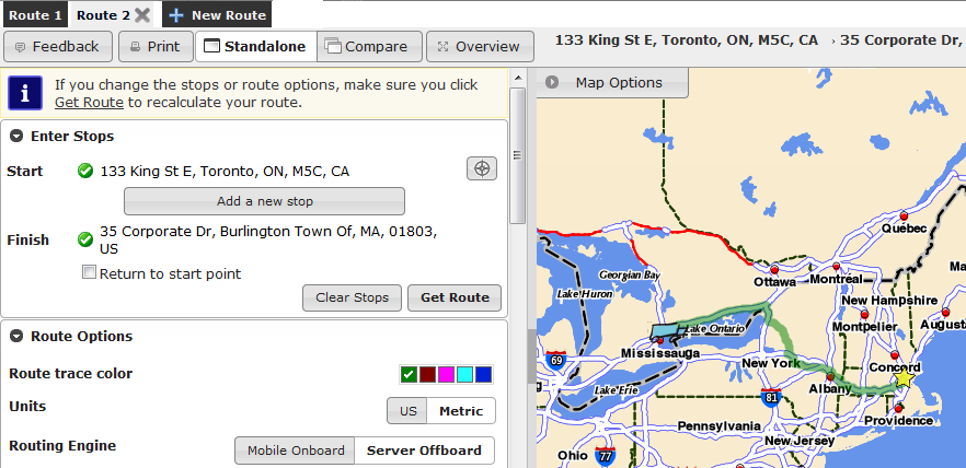
Generating a Route
To generate a route using Route Generator, follow these steps:
Use the Enter Stops panel to specify a starting point, and a destination or at least one stop.
Optionally, you can modify your Route Options.
Click the Get Route button to generate your route.
To generate another route, click the New Route button.
A new route tab appears, allowing you to generate a new route without closing other generated routes. To switch to between generated routes, click the route tab.
To close a route tab, click the X within the tab.
Printing a Route
After you have successfully generated a route, you can print your route.
To print a route, click the Print button just below the tabs at the top of the Route Generator screen.
When you click the Print button, a Print Directions dialog appears.
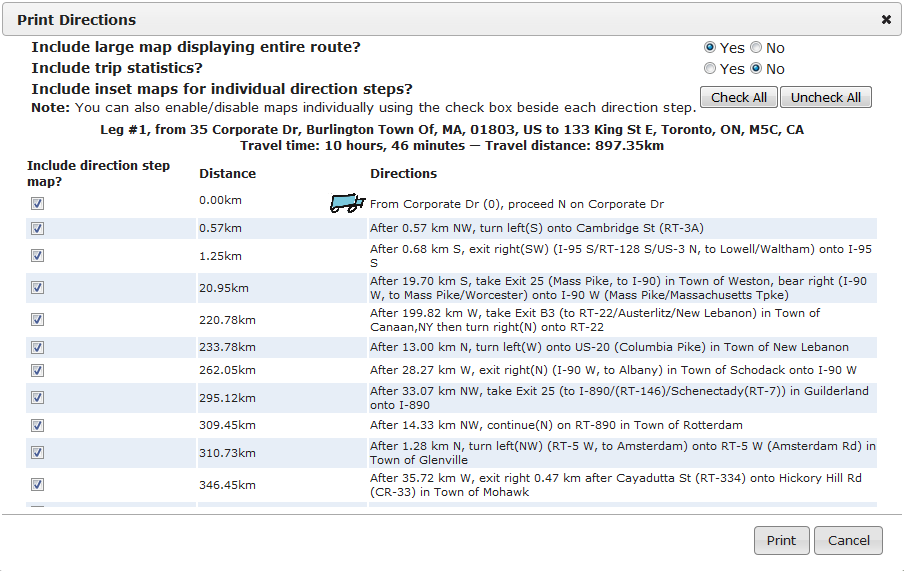
The Print Directions dialog allows you to adjust the following print options:
Include large map displaying entire route?: Includes a large map that displays an overview of the entire route.Include trip statistics?: Includes trip statistics on the printed route.Include inset maps for individual direction steps?: Includes small maps for each individual direction. You can manually check/uncheck the option beside each direction, or use the Check All and Uncheck All buttons to quickly enable or disable all directions.
After you have selected your print options, click the Print Route button to print the route using the selected print options.
Opening an Existing Route
From NaviGo Monitor, you can open a requested or generated route in Route Generator by clicking the Modify button. This allows you to recreate the route and experiment with different route options. You can revert to the original options at any time, or return to viewing the route in NaviGo Monitor.
When you open an existing route in Route Generator, an Original Route Details panel appears at the top of the route tab.
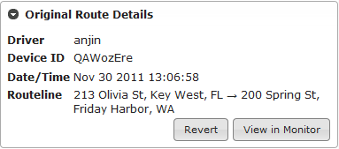
A Map Options panel also appears.
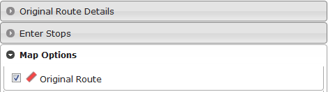
The Original Route Details panel provides the following information about the route:
Driver: The ID of the driver logged into NaviGo when the request was received.Device ID: The ID of the device that submitted the request.Date/Time: The date and time of the route request.Routeline: The starting point and destination of the route request.
With the original route displayed, you can now:
Use the Enter Stops panel to change the starting point and destination, and add stops.
Modify your Route Options.
Click the Get Route button to generate the modified route.
The original route will continue to be displayed on the map in red, and the modified route will be displayed using the selected trace color.
To hide the original route trace on the map, expand the Map Options panel and uncheck the Original Route option.
To revert to the original route, click the Revert button within the Original Route Details panel. The original route options will be reapplied with the following exceptions:
Avoid turns at start of route?Modifier ModeUnitsAllow fall back to non-HazMat safe routing?all of the
Fuel Plan Settings
Any changes made to these options in Route Generator will be retained.
To return to viewing the route in NaviGo Monitor, click the View in Monitor button.
Comparing Routes
You can compare two routes side by side by clicking the Compare button. The Compare button appears at the top of the Route Generator screen, just below the route tabs.
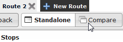
When you click the Compare button, the left side of the screen divides into two panels: one labeled Original Route and one labeled Comparison Route. Initially, the comparison route will be a copy of the original route.
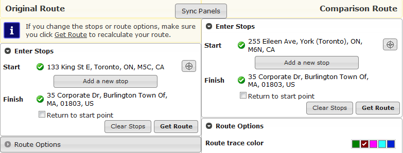
In each panel, you can:
Use the Enter Stops panel to specify a starting point, and at least one stop or a destination.
Optionally, you can modify your Route Options.
Click the Get Route button to generate the route.
Both routes will be displayed on the same map, with different trace colors being used for each route.
Note: Where the two routes overlap, the two trace colors are combined. For example, if green and purple are used to trace two routes, the common segments will appear brown.
If the Sync Panels option is active (a checkmark will appear beside the button label), the settings for the comparison route will be automatically updated with any changes you make to the original route's settings.
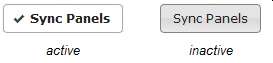
To return to displaying only the original route, click the Standalone button.
Adding a Road Modifier
Within Route Generator, you can choose a location to create a road modifier. You'll be taken to Road Manager where you can finish creating the modifier using the location you chose.
To start the process of adding a road modifier, follow these steps:
Zoom the Route Generator map to a level between 12 and 15.
Left click the map where you want the road modifier to be located.
From the dialog that appears, click Create modifier here.
Road Manager will appear with the location you chose entered as a first waypoint for the modifier.
From Road Manager, provide the remaining information required to create the modifier.
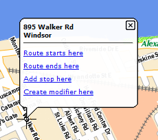
Route Generator Buttons
The following buttons appear just below the tabs at the top of the Route Generator screen.
Table 13. Route Generator Buttons
| Button | Description |
|---|---|
| Feedback | Allows you to provide feedback on the generated routes. When you click this button, a window appears in which you can enter your comments. From this window, click Submit to send us your feedback. |
Allows you to print your route. This button is only available after you have generated your route. From the Print Directions dialog that appears, you can adjust following print options then click Print Route button to print the route. For more information, see Printing Routes. | |
| Standalone | Returns to displaying the original route only after clicking the Compare button to compare routes side by side. |
| Compare | Allows you to compare two routes side by side. For more information, see Comparing Routes. |
Enter Stops Panel
In the Enter Stops panel, you enter the starting point for your route, and either a destination or one or more stops.
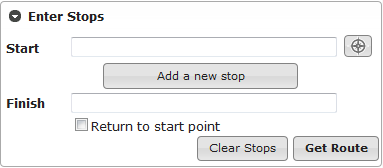
To enter your route stops, perform the following steps:
Specify your route's starting point using one of the following methods:
Enter your starting location in the
Startfield. You can specify the location in a variety of different ways. For more information, see Specifying Locations.Click on the map where you want the route to begin and select Route starts here. The map will automatically zoom to the selected location.
After you have successfully geocoded your start address, you can Set the Initial Travel Direction.
(optional) Add stops to your route using one of the following methods:
Click Add a new stop. In the field that appears, enter the location of the stop. For information on the different ways you can specify locations, see Specifying Locations.
Click on the map at the stop location and select Add stop here. The map will automatically zoom to the selected location.
Repeat these steps if you want to add additional stops to your route. If you want to delete a stop, click the Delete button beside the stop that you wish to delete.
Specify your route's destination using one of the following methods:
Enter the location in the
Finishfield. For information on the different ways you can specify locations, see Specifying Locations.Click on the map where you want the route to end and select Route ends here. The map will automatically zoom to the selected location.
If you would like your route to end back at the starting point, select the
Return to start pointoption by placing a checkmark in the box. After you have selected it, your starting point will be copied into theFinishfield.
Click Get Route.
To clear the stops and generate a different route, click Clear Stops.
Prior to clicking the Get Route button, you may wish to change your Route Options.
If the route generator cannot locate an address that you specified, an error message is displayed. If a location that you specified is ambiguous, the candidates addresses will be displayed so you can select the correct one.
When your route request is successful, the directions will appear in the Directions panel.
Specifying Locations
You can specify your start location, stop locations, or destination location in a variety of different ways. The OneBox service will interpret your input and return the closest matching address.
OneBox understands a wide variety of inputs so you can quickly and easily specify a location. Here are some well-formed common input examples:
35 Corporate Drive, Burlington, MA: Comma-separated address providing street, city, and region information
@maptuit: Searches for a POI (triggered by @ symbol) with a maptuit ID.
fuel: Searches for fuel stations ahead (if a route is available), or nearby
-79.37295,43.65023: Searches for the specified coordinates.
sushi near toronto, on: Searches for sushi keyword near Toronto, On. Refer to the OneBox Documentation for a full list of available keywords.
For a complete list of acceptable inputs, and additional information about OneBox, see the OneBox Documentation.
Setting the Initial Travel Direction
After you have specified and geocoded the starting point of your route, you can specify the initial travel direction.
To specify the initial travel direction, perform the following steps:
Click the compass icon located beside the start address:
After you click the icon, the map centers on your start address.
Click a location on the map that indicates the direction you will be traveling from the starting point. An arrow appears on the starting point indicating the new direction of travel. The direction is also displayed within the Enter Stops panel.
Click the Save travel direction button (located on the left hand side of the screen) to save the travel direction, or click the Cancel and remove travel direction button to cancel and disregard the selected travel direction.
Route Options Panel
From the Route Options panel, you can change the parameters that influence route selection.
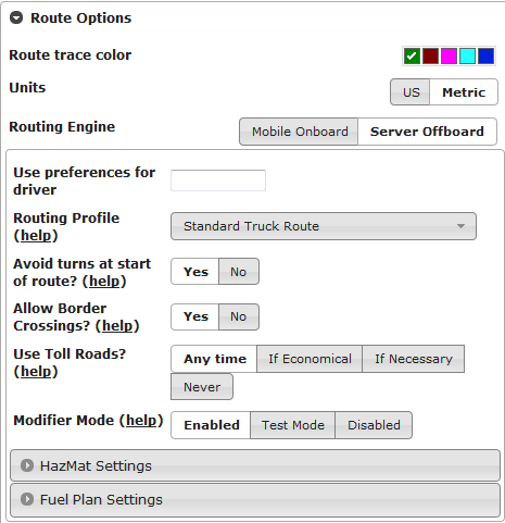
Note: After modifying route options, click the Get Route button to recalculate the route.
The Route Options panel allows you to modify the following parameters:
Table 14. Route Options
| Option | Description |
|---|---|
| Route trace color | Choose the color used to trace the route on the map. When you compare two routes side by side, different colors are used for each route. |
| Units | Indicate whether to use US (imperial) or metric units of measurement. |
| Routing Engine | Choose whether to generate a routing using the offboard server or the onboard routing engine.
Choosing the Mobile Onboard routing engine allows you to reproduce routes that
were generated onboard. Depending on the routing engine you choose, different routing options appear. |
Mobile Onboard Options
These options allow you to reproduce a route generated using the onboard routing engine.
Table 15. Mobile Onboard Options
| Option | Description |
|---|---|
| Data Version | The version number of onboard dataset to be used to reproduce the route. |
| Favor Truck Roads | Indicate whether to favor truck roads over faster routes. |
| Ignore Obstructions | Indicate whether to ignore modifiers and truck restrictions. |
| Allow Border Crossings | Indicate whether to allow border crossings on your route. When this option is selected, routes are allowed to cross international borders to save distance even when all stops are in the same country. |
| Discourage Toll Roads | Indicate whether to avoid toll roads and toll bridges on the route. |
Server Offboard Options
These options allow you to generate a route using the offboard server.
Table 16. Server Offboard Options
| Option | Description |
|---|---|
| Use preferences for driver | Enter a driver's ID to apply the preferences stored for that driver. Driver preferences are maintained using the Driver Management application,
and can include the routing profile. If you select a different routing profile using the Routing profile option below, the driver's preferred profile will be ignored. |
| Routing profile | Choose the routing profile you want to use. If you entered a driver ID in
|
| Avoid turns at start of route | Indicate whether your route should avoid turns at the start of the route. When enabled, turns are discouraged during the first few moments of the route. This extra time allows the driver to move away from the origin in a specific direction while the route is generated. |
| Allow Border Crossings | Indicate whether you want to restrict border crossings on your route. When enabled, routes are allowed to cross international borders to save distance even when all stops are in the same country. |
| Use Toll Roads |
Choose when to include toll roads and toll bridges as part of the route.
|
| Modifier Mode | Indicate whether to enable road modifiers and truck restrictions when generating the route.
|
HazMat Settings
The following HazMat options are available only when the Server Offboard routing engine is selected.
Table 17. HazMat Settings
| Option | Description |
|---|---|
| Allow fallback to non-HazMat safe routing? | Indicate whether to allow non-HazMat compliant routes to be included if one or more HazMat material classes are selected and a HazMat compliant route cannot be found. |
| HazMat Classes |
If you are transporting hazardous material, select one or more HazMat material classes so that a HazMat-compliant route can be generated.
To select one or more HazMat classes, click one or more of the HazMat class symbols.
Maptuit's HazMat routing service uses a HazMat trunk network, consisting of all STAA roads, augmented with Navteq-defined HazMat-preferred road segments. The goal of the HazMat routing service is to route the unit as quickly as possible to this trunk network, and remain on the trunk network for the majority of the route. After the vehicle has reached the end of the hazardous trunk network, the unit is routed using standard truck routing to the specified destination. At all times during the route, all known HazMat-forbidden roads are avoided for specified hazardous material types passed to the routing service.
If an unbroken, HazMat-friendly route cannot be found between the origin and destination for the selected HazMat classes, the HazMat service defaults to normal routing behavior.
If the HazMat route cannot be generated, a fall-back route will be provided if the
|
Fuel Plan Settings
Allows you to enable fuel planning by indicating the current fuel level of the vehicle.
Table 18. Fuel Plan Settings
| Option | Description |
|---|---|
| Tank Level | The current level of the vehicle's fuel tank. |
| Tank Capacity | The capacity of the vehicle's fuel tank. |
| Economy | The fuel economy of the vehicle. |
| Minimum Purchase | The minimum amount of fuel to purchase each time the vehicle is refueled. |
| Network | The fuel network to use for fuel stops. |
Directions Panel
The Directions panel provides the text directions for your route, and allows you to view individual directions on the map.
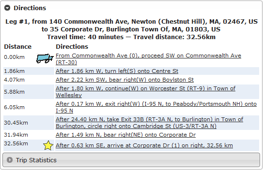
While viewing your route, you add or modify stops by clicking the Enter Stops panel, and change your route option from the Route Options panel.
You can click View Entire Route at any time to view the map and text directions for the entire route. You can also click individual directions steps to view that direction step on the map.
Explain Modifiers Panel
The Explain Modifiers panel provides information about road modifiers that are located directly on the generated route.
Important: This feature provides information about modifiers that are located directly on the generated route, regardless of whether or not the road modifiers actually affected the generated route. For example, in many cases the most optimal route is not chosen due to various forbid or avoid modifiers. However, those modifiers will likely not appear in the Explain Modifiers panel because the generated route avoided those areas or turns. Therefore, those forbid/avoid modifiers are not listed in the Explain Modifiers panel because they do not appear directly on the generated route.
After you have generated a route, the following link appears in the Explain Modifiers panel: Click to retrieve modifier explanation. Click the link to generate a list of modifiers that are located on the route.
Note: For performance reasons, this feature is not activated automatically. You must click the link in the panel to display the list of modifiers.
After clicking the link, the Explain Modifiers panel expands to display the following information for each road modifier:
Source Owner: The source of the modifier. The modifier source can be navteq, maptuit, or one of your own fleets.Name (ModifierId): The name and ID of the modifier. This information is presented as a link. Click the link to center and zoom the map on the location of the modifier.Category: The category of the modifier.
To view detailed information about the modifier in Road Manager, click the ![]() icon beside the modifier name.
icon beside the modifier name.
Refer to the Road Manager User Guide for more information about modifier categories.
Map Options Panel
The Map Options panel allows you to control the elements and information that are displayed on the map. The Map Options panel is located in the top left hand corner of the map. Click the Map Options button to open or close the Map Options panel.
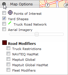
Note: To enhance map performance, some map options are only available at a minimum scale level. If you are zoomed out too far for a particular map option, the option is grayed out and no longer available. After you zoom in to a certain level, the option will become active again.
The following map options are available from Route Generator.
Table 19. Map Options
| Options | Description |
|---|---|
| Points of Interest | Displays your fleet's points of interest on the map. These do not include NAVTEQ POIs or fuel POIs. POIs are displayed on the map using a bullseye icon. Points of interest can be viewed at map scale levels 7 and above. |
| Yard Shape | Displays the location of yards. Yards appear on the map in blue. Yard shapes can be viewed on the map at scale levels 6 and above. |
| Truck Road Network | Displays the truck road network. Truck roads appear on the map in green. The truck road network can be viewed on the map at scale levels 7 and above. |
| Aerial Imagery | Displays the map using aerial imagery. When this option is enabled, you can use the slide bar to control the degree of aerial imagery transparency. Aerial imagery can be displayed at all map scale levels but is only available for maps of the USA and some portions of Canada. |
| Truck Restrictions | Displays NAVTEQ truck restrictions on the map. Only those that apply to STAA-approved, non-HazMat roads are shown. Truck restrictions, like other road modifiers, appear in brown on the map. Truck restrictions can be viewed at map scale levels 7 and above. |
| NAVTEQ HazMat | Displays NAVTEQ's HazMat-designated and HazMat-restricted road segments on the map. NAVTEQ's HazMat road segements can be viewed at map scale levels 7 and above. |
| Maptuit Global | Displays Maptuit's global road modifiers on the map. Maptuit's modifiers are drawn from our data sources, including feedback from drivers. Maptuit global modifiers can be viewed at map scale levels 7 and above. |
| Maptuit Global HazMat | Displays Maptuit's HazMat-designated and HazMat-restricted road segments on the map. Maptuit's HazMat road segements can be viewed at map scale levels 7 and above. |
| Fleet Modifiers | Displays your fleet's road modifiers on the map. Your fleet's modifiers can be viewed on the map at scale levels 7 and above. |
Tools
NaviGo Portal offers you a variety of tools for maintaining your fleets:
Driver Management: manage drivers using operations such as search, create, edit and delete.
Fleet Preferences: manage fleets, sub-fleets, routing profiles, portal users, and fleet defaults using the following sub-applications:
Usage Report: obtain statistical information about NaviGo usage.
Driver Management
The driver management application allows you to search for drivers, create new drivers, edit existing drivers, and delete drivers.
The driver management page looks like this:
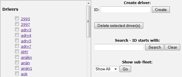
On the Driver Management page, existing driver IDs and virtual driver IDs are displayed on the left hand side of the page. Existing drivers are those that already have an existing configuration. Virtual drivers are those that do not already have a configuration.
You can click on a driver ID to create or edit the configuration for the driver. If you click a driver ID that already has a configuration, the Edit screen is displayed. If you click a virtual driver (i.e. with no existing configuration), the Create screen is displayed.
You can view the drivers that belong to a sub-fleet by selecting a sub-fleet from the Show sub-fleet drop down list.
Then, click Go to display the list of drivers that belong to the selected sub-fleet.
Creating Drivers
To create a new driver, perform the following steps:
Type the new driver ID into the
Create driver IDfield, and then click the Create button. If the driver ID already exists, you will receive the following error:A driver with the ID already exists. You may not create a new driver with the same ID
If the driver ID is valid, the create driver page is displayed.
Note: You can also access the Create screen by clicking on a Driver ID of a virtual driver. This will allow you to create a configuration for the driver.
Complete the fields on the driver creation page:
Driver's first name: Defines the driver's first name.Note: This field is required.
Driver's last name: Defines the driver's last name.Note: This field is required.
Password: Defines the driver's password.Play chime before reading direction: Defines whether or not a chime is played prior to reading a direction step.Routing profile: Defines the routing profile of the driver.
You can use the Enable and Disable buttons to enable and disable fields. Some fields are Required and cannot be enabled/disabled.
To save the driver, click Save Changes. To cancel the driver creation, click Cancel.
Editing Drivers
To edit a driver, perform the following steps:
Click on the driver ID located on the left hand side of the screen. If the driver ID is not displayed, or if there is a long list of drivers, you can Search for Drivers to locate the driver that you wish to edit. After you click the driver ID, the Edit screen is displayed.
Note: If the driver ID that you selected is a virtual driver, the Create screen is displayed so you can create a configuration for that driver.
Tip: Refer to the
Last Changeinformation in the top right hand corner of the Edit screen to view the username and date/time of the last changes that were saved.Edit the fields that you wish to modify on the driver edit page:
Driver's first name: Defines the driver's first name.Note: This field is required.
Driver's last name: Defines the driver's last name.Note: This field is required.
Password: Defines the driver's password.Play chime before reading direction: Defines whether or not a chime is played prior to reading a direction step.Routing profile: Defines the routing profile of the driver.
You can use the Enable and Disable buttons to enable and disable fields. Some fields are Required and cannot be enabled/disabled.
To save the driver, click Save Changes. To cancel the driver changes, click Cancel.
Deleting Drivers
To delete drivers, perform the following steps:
Select one or more drivers by placing a checkmark in the box beside the driver ID of each driver that you wish to delete. If a driver ID that you wish to delete is not displayed, or if there is a long list of drivers, you can Search for Drivers to locate the driver(s) that you wish to delete.
Click Delete Selected Driver(s). A confirmation message asks you Are you sure you want to delete the selected driver(s)?
Click OK if you want to delete the driver(s) that you selected. Otherwise, click Cancel.
Fleet Preferences
The Fleet Preferences application allows you to manage fleets, sub-fleets, portal users, and fleet defaults.
Note: You must be logged into an Administrator or Reseller account in order to see the Fleet Preferences option on the tools menu.
When you load the Fleet Preferences application, the Fleet Defaults tab is displayed automatically. There are other tabs available in Fleet Preferences such as Fleet Management, Portal Users, and Subfleet Management.
Fleet Management
The Fleet Management tool allows you to manage your fleets.
Note: You must have
Reselleraccess in order to see the Fleet Management tab on the Fleet Preferences screen.
You can access the Fleet Management screen by clicking the Fleet Management tab on the Fleet Preferences screen. The Fleet Preferences screen is accessible by clicking the Fleet Preferences option on the Tools menu.
The Fleet Management tool looks like this:
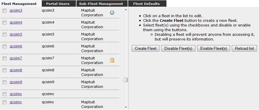
The Fleet Management screen displays a list of all fleets, as well as the fleet name, id, and status. The status is represented using the following icons:
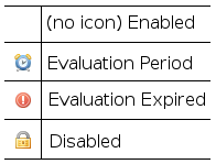
The right hand side of the screen allows you to perform various operations such as creating new fleets, editing fleets, disabling fleets, and enabling fleets.
Simply click on fleet name to view or edit the fleet information.
Tip: Click the column headers (Fleet Name, Fleet ID, Fleet Status) to sort the information in either ascending or descending order.
Creating a New Fleet
To create a new fleet, perform the following steps:
Click the Create Fleet button on the Fleet Management screen.
Complete the fields on the fleet creation page:
Create Fleet Fields:
Fleet ID: Defines the short unique identifier for the fleet. This field must not contain spaces or special characters.Fleet Name: Defines the descriptive name for the fleet. For example, the company name.Hardware Device: Defines the hardware device that the fleet will use.Enabled Features: Defines the portal features and map options that will be available for the fleet.Yardswill enable the Yard Shaper in POI Editor, and allow yards to be displayed as Map Options throughout the portal.NaviGo Basic Eventswill enable NaviGo event reporting for the fleet, and will allow the basic event types (Feedback, Activity, Route Request, and Search) to be displayed as Map Options throughout the portal.NaviGo Compliance Eventswill enable compliance and position event reporting for the fleet, and allow these event types to be displayed as Map Options throughout the portal.HazMat Routingwill allow the fleet to request routes for various hazardous material types, and allow HazMat-related modifiers to be displayed as Map Options throughout the portal.Road Manager Editor: Defines whether or not to enable the Road Manager application for the new fleet.Note: Individual portal users must be granted access to Road Manager from the Portal Users page.
Driver Address Editor: Defines whether or not to enable the Driver Addresses application for the new fleet.Fuel Stop Editor: Defines whether or not to enable the Fuel Stations application for the new fleet.Allow fallback to non-HazMat safe routing: If selected, when a HazMat-compliant route is requested but cannot be generated, a non-HazMat truck route may be generated instead. The driver will be alerted and asked to accept or reject the non-HazMat route.Default routing profile: Defines the default routing profile for the new fleet. If not defined, the default routing profile for the new fleet will be set toStandard Truck Route.Enable driver management API?: Defines whether or not to enable driver management API.Enable Evaluation: Defines whether or not the fleet is created as an evaluation account. If this feature is enabled, you can specify the number of days that the account shall remain active.Expiry Date: Use the calendar tool to define the date when the evaluation shall expire.
Client Authentication Fields:
Shared Fleet Password: Defines the shared fleet password that is used to authenticate any undefined driver account.Shared Fleet Password (again to verify): This password must exactly match the field above.
Portal Administrator Fields:
Note: The portal administrator fields should only be completed if you wish to create an administrator account for the new fleet. The portal administrator account will have access to all Portal applications with administrator privileges.
Account ID: Defines the account ID. This ID must be a short unique identifier that does not contain spaces or special characters.Account First Name: Defines the first name of the portal administrator.Account Last Name: Defines the last name of the portal administrator.Account Email Address: Defines the email address of the portal administrator.Account Password: Defines the account password.Account Password (to verify): This value must match the value of the above field.
Portal Single Sign-on Authentication Fields:
Single Sign-on Key: Defines the key used for single sign-on authentication purposes.Note: After you set this key, you cannot modify it. Speak to your Maptuit customer support representative for more information.
Single Sign-on Default Applications: Defines the default applications that use single sign-on authentication. You can click the Select All to select all applications.
To save the fleet, click Save. To cancel the fleet creation, click Cancel.
Editing a Fleet
To edit a fleet, perform the following steps:
Click on the fleet name located on the left hand side of the screen. After you click the fleet name, the Modify Fleet page is displayed.
Edit the fields that you wish to modify:
Fleet IDNote: You cannot modify the Fleet ID!
Fleet Name: Defines the descriptive name for the fleet. For example, the company name.Shared Fleet Password: Defines the shared fleet password that is used to authenticate any undefined driver account.Shared Fleet Password (again to verify): This password must exactly match the field above.Single Sign-on Key: Defines the key used for single sign-on authentication purposes.Note: You cannot modify this key. Speak to your Maptuit customer support representative for more information.
Single Sign-on Default Applications: Defines the default applications that use single sign-on authentication. You can click the Select All to select all applications.
To save the fleet changes, click Save. To cancel the fleet changes, click Cancel.
Disabling a Fleet
Disabling a fleet prevents others from accessing the fleet, but preserves the fleets information. This allows you to enable and use the fleet again at a later time.
Note: You cannot delete a fleet. If you no longer require a fleet, you have the ability to disable the fleet. After a fleet is disabled, the fleet can no longer be used unless it is re-enabled.
To disable a fleet, perform the following steps:
On the Fleet Management screen, place a checkmark beside the fleet that you wish to enable.
Click the Disable Fleet button.
The system asks you if you wish to disable the selected fleet(s). Click OK to disable the fleet(s), or Cancel to cancel the operation.
Enabling a Fleet
Enabling a fleet allows you to use a fleet that was previously disabled.
To enable a fleet, perform the following steps:
On the Fleet Management screen, place a checkmark beside the fleet that you wish to enable.
Click the Enable Fleet button.
Sub-Fleet Management
The Sub-Fleet Management screen allows you to search for sub-fleets, create new sub-fleets, edit existing sub-fleets, and delete sub-fleets.
Note: You must have
Administratoraccess in order to see the Sub-Fleet Management tab on the Fleet Preferences screen.
To access the Sub-Fleet Management screen, click the Sub-Fleet Management tab within the Fleet Preferences application.
The Sub-Fleet Management screen looks like this:
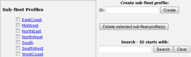
Existing sub-fleet IDs are displayed on the left hand side of the page. You can click on a sub-fleet ID to view or edit the sub-fleet information. The right hand side of the page allows you to perform various operations such as creating sub-fleets, searching for sub-fleets, or deleting sub-fleets.
Creating Sub-Fleets
To create a new sub-fleet, perform the following steps:
Type the new sub-fleet ID into the
Create sub-fleet profilefield.Click Create.
If the sub-fleet ID already exists, an error displays because you cannot create a sub-fleet with the same ID. If the sub-fleet ID is valid, the create sub-fleet page is displayed.
Enable all of the settings that you wish to specify.
You can enable settings by clicking the Enable button that is displayed on the right hand side of each setting. Disabled settings are grayed out, while enabled settings allow you to modify them.
Modify the settings:
Table 20. Settings
Parameter Description Values Routing profileDefines the default routing profile.
This value can be set to one of the following routing profiles:
Standard Truck Route: Selects the most practical truck route.Shorter Truck Route: Selects shorter routes over faster routes, using truck roads.Shortest Truck Route: Selects the shortest route, with less emphasis on the use of truck roads and toll roads.Faster Truck Route: Selects faster routes over shorter routes, using truck r oads and major highways.Fastest Truck Route: Selects the fastest truck route, using freeways, truck roads, and toll roads.FleetNav Default: Selects a route using your existing FleetNav routing settings.Note: This option appears only for fleets that migrated their existing FleetNav settings when the fleet was created. Contact your Maptuit customer support representative for more information.
Allow border crossingDefines whether or not to allow border crossing.
This value can be set to
YesorNo.Play chime before reading directionDefines whether or not to play a chime prior to reading directions.
This value can be set to
YesorNo.Distance allowed before out-of-range (in metres)Defines the distance that is allowed prior to out-of-range.
This value can be set to an Integer, measured in metres.
Units to display distance values inDefines the unit that will be used when displaying values.
This value can be set to
MilesorKilometres.To save the sub-fleet, click Save Changes. To cancel the sub-fleet creation, click Cancel.
Editing Sub-Fleets
To edit a sub-fleet, perform the following steps:
Click on the sub-fleet ID located on the left hand side of the screen. If the sub-fleet ID is not displayed, or if there is a long list of sub-fleets, you can Search for Sub-Fleets to locate the sub-fleets that you wish to edit. After you click the sub-fleet ID, the edit page is displayed.
Edit the fields that you wish to modify on the sub-fleet edit page. When you are editing a sub-fleet, fields that are already defined are enabled, and fields that are not yet defined are disabled.
To save the sub-fleet, click Save Changes. To cancel the sub-fleet creation, click Cancel.
Deleting Sub-Fleets
To delete sub-fleets, perform the following steps:
Select one or more sub-fleets by placing a checkmark in the box beside the sub-fleet ID of each sub-fleet that you wish to delete. If a sub-fleet ID that you wish to delete is not displayed, or if there is a long list of sub-fleets, you can Search for Sub-Fleets to locate the sub-fleet(s) that you wish to delete.
Click Delete selected sub-fleet profile(s). A confirmation message asks you
Are you sure you want to delete the selected sub-fleet profile(s)?Click OK if you want to delete the sub-fleet profile(s) that you selected. Otherwise, click Cancel.
Portal Users
The Portal Users page allows you to perform a number of user operations, such as creating a new portal user, editing users, deleting users and disabling users.
Note: You must have
Administratoraccess in order to see the Portal Users tab on the Fleet Preferences screen.
To access the Portal Users page, click the Portal Users tab on the Fleet Preferences screen.
The Portal Users screen looks like this:
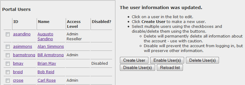
Existing portal users are displayed on the left hand side of the page.
Tip: Click the column headers (ID, Name, Access Level, Disabled) to sort the information in either ascending or descending order.
The right hand side of the page allows you to perform various operations such as creating new drivers, searching for drivers, or deleting drivers. You can click Reload List on the Portal Users page to reload the list of users that are displayed on the left hand side of the page.
Creating Users
To create a new user, perform the following steps:
Click Create User.
Enter the new user information on the Create User page:
Login ID: Defines the Login ID of the new user.First Name: Defines the user's first name.Last Name: Defines the user's last name.E-Mail address: Defines the user's e-mail address. The e-mail address is used in order to recover a forgotten password. This field is optional.New Password: Defines the password of the new user.New Password (again to verify): Verifies that you typed the password correctly. The passwords must match in order for the user creation to be successful.Disabled?: Defines whether or not the user status is set to disabled.Admin Access: Defines whether or not the user has administrator access. Administrator access allows the user to access the Sub-Fleet Management, Portal Users and Fleet Defaults tabs located on the Fleet Preferences screen.Note: Admin Access is automatically granted if Reseller Access is enabled.
Reseller Access: Defines whether or not the user has reseller access. Accounts with reseller access have the ability to use the Fleet Management tool.Important: Accounts with Reseller Access are automatically granted admin access.
Accessible Applications: Defines the applications that the user will have access to. You can click Select All to select all of the applications in the list.Portal opens to: Defines the page that opens when the user logs in to NaviGo Portal.
Click Save to create the new user, or click Cancel to discard.
Editing Users
To edit a user, perform the following steps:
Click user's login ID or Name that you wish to edit. The Modify User page is displayed.
Edit the user information by modifying the fields that you wish to change.
Click Save to accept the changes, or Cancel to discard the changes.
Disabling Users
To disable user(s), perform the following steps:
Select one or more portal users by placing a checkmark in the box beside the user ID of each user that you wish to disable.
Click Disable User(s). A confirmation message asks you
Are you sure you want to disable the selected user(s)?Click OK if you want to disable the user(s) that you selected. Otherwise, click Cancel.
Deleting Users
To delete user(s), perform the following steps:
Select one or more portal users by placing a checkmark in the box beside the user ID of each user that you wish to delete.
Click Delete User(s). A confirmation message asks you
Are you sure you want to delete the selected user(s)?Click OK if you want to delete the user(s) that you selected. Otherwise, click Cancel.
Fleet Defaults
The Fleet Defaults allows you to set default values for your fleet, such as default routing profile.
Note: You must have
Administratoraccess in order to see the Fleet Defaults tab on the Fleet Preferences screen.
The Fleet Defaults screen looks like this:
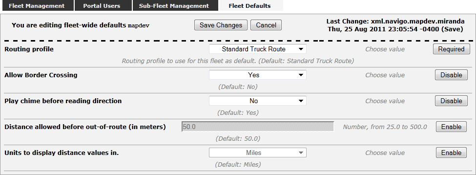
Tip: Refer to the Last Change information in the top right hand corner of the tab to view the username and date/time of the last changes that were saved.
To set fleet defaults on the Fleet Defaults screen, perform the following steps:
Enable all of the setting that you wish to specify a default value.
You can enable the default values by clicking the Enable button that is displayed on the right hand side of each setting. Disabled settings are grayed out, while enabled settings allow you to modify them.
Modify the fleet default values:
Table 21. Settings
Parameter Description Values Routing profileDefines the default routing profile.
This value can be set to one of the following routing profiles:
Standard Truck Route: Selects the most practical truck route.Shorter Truck Route: Selects shorter routes over faster routes, using truck roads.Shortest Truck Route: Selects the shortest route, with less emphasis on the use of truck roads and toll roads.Faster Truck Route: Selects faster routes over shorter routes, using truck r oads and major highways.Fastest Truck Route: Selects the fastest truck route, using freeways, truck roads, and toll roads.FleetNav Default: Selects a route using your existing FleetNav routing settings.Note: This option appears only for fleets that migrated their existing FleetNav settings when the fleet was created. Contact your Maptuit customer support representative for more information.
Allow border crossingDefines whether or not to allow border crossing.
This value can be set to
YesorNo.Play chime before reading directionDefines whether or not to play a chime prior to reading directions.
This value can be set to
YesorNo.Distance allowed before out-of-range (in metres)Defines the distance that is allowed prior to out-of-range.
This value can be set to an Integer, measured in metres.
Units to display distance values inDefines the unit that will be used when displaying values.
This value can be set to
MilesorKilometres.When you are finished setting your fleet defaults, click the Save Changes button to save your changes, or click the Cancel button to discard your changes.
Usage Report
The Usage Report Tool allows you to view graphs and data about the usage of the system. You can create the following usage reports:
All Fleet Usage Report: Provides usage information for all fleets.Per Sub-Fleet Report: Provides usage information for a particular sub-fleet.Per Driver Report: Provides usage information for a particular driver.Per Device Report: Provides usage information for a particular device.All Fleets Summary Report: Contains summary usage information for all fleets.Note: You must have Reseller privileges to generate the
All Fleets SummaryReport.
The usage report tool looks like this:
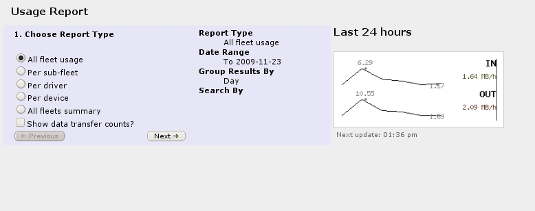
Generating Reports
Report by Fleet
To generate a usage report for all fleet usage, perform the following steps:
Select
All fleet usagefor theReport Type.Select the
Show data transfer counts?option if you would like your report to display the data transfer information.Click the Next button.
Specify the report
Date Rangeby choosing a date for theFromandTofields. You can click the calendar icon to select the dates.Click the Next button.
Select one of the following
Group Results Byoptions:Hour: Report data will be grouped by hour.Day: Report data will be grouped by day.Week: Report data will be grouped by week.Month: Report data will be grouped by month.
Place a checkmark in the
Sub-group by device typeoption if you want your report data grouped by device type.If you select this option, the data for each date will be grouped by device type.
Click the Generate Report button to generate the report using the values that you specified. You can also use the Previous button to change report parameters.
Report by Sub-Fleet
To generate a usage report for a particular sub-fleet, perform the following steps:
Select
Per Sub-Fleetfor theReport Type.Select the
Show data transfer counts?option if you would like your report to display the data transfer information.Click the Next button.
Specify the report
Date Rangeby choosing a date for theFromandTofields. You can click the calendar icon to select the dates.Click the Next button.
Select one of the following
Group Results Byoptions:Hour: Report data will be grouped by hour.Day: Report data will be grouped by day.Week: Report data will be grouped by week.Month: Report data will be grouped by month.
Place a checkmark in the
Sub-group by device typeoption if you want your report data grouped by device type.If you select this option, the data for each date will be grouped by device type.
Click the Next button.
Select a sub-fleet from the
Limit Sub-Fleetdrop down list.Click the Generate Report button to generate the report using the values that you specified. You can also use the Previous button to change report parameters.
Report by Driver
To generate a usage report for a particular driver, perform the following steps:
Select
Per Driverfor the Report Type.Select the
Show data transfer counts?option if you would like your report to display the data transfer information.Click the Next button.
Specify the report
Date Rangeby choosing a date for theFromandTofields. You can click the calendar icon to select the dates.Click the Next button.
Select one of the following
Group Results Byoptions:Hour: Report data will be grouped by hour.Day: Report data will be grouped by day.Week: Report data will be grouped by week.Month: Report data will be grouped by month.
Place a checkmark in the
Sub-group by device typeoption if you want your report data grouped by device type.If you select this option, the data for each date will be grouped by device type.
Click the Next button.
Specify the driver ID in the
Limit driversfield, or leave the field blank to indicate all drivers.Click the Generate Report button to generate the report using the values that you specified. You can also use the Previous button to change report parameters.
Report by Device
To generate a usage report for a particular device, perform the following steps:
Select
Per Devicefor theReport Type.Select the
Show data transfer counts?option if you would like your report to display the data transfer information.Click the Next button.
Specify the report
Date Rangeby choosing a date for theFromandTofields. You can click the calendar icon to select the dates.Click the Next button.
Select one of the following
Group Results Byoptions:Hour: Report data will be grouped by hour.Day: Report data will be grouped by day.Week: Report data will be grouped by week.Month: Report data will be grouped by month.
Place a checkmark in the
Sub-group by device typeoption if you want your report data grouped by device type.If you select this option, the data for each date will be grouped by device type.
Click the Next button.
Specify the device ID in the
Limit devicesfield, or leave the field blank to indicate all devices.Click the Generate Report button to generate the report using the values that you specified. You can also use the Previous button to change report parameters.
All Fleets Summary Report
To generate an all fleets summary report, perform the following steps:
Select
All fleets summaryfor the Report Type.Select the
Show data transfer counts?option if you would like your report to display the data transfer information.Click the Next button.
Specify the report
Date Rangeby choosing a date for theFromandTofields. You can click the calendar icon to select the dates.Click the Next button.
Select one of the following
Group Results Byoptions:Hour: Report data will be grouped by hour.Day: Report data will be grouped by day.Week: Report data will be grouped by week.Month: Report data will be grouped by month.
Place a checkmark in the
Sub-group by device typeoption if you want your report data grouped by device type.If you select this option, the data for each date will be grouped by device type.
Click the Generate Report button to generate the report using the values that you specified. You can also use the Previous button to change report parameters.
Report Results
After you have successfully generated a report, you can sort the data by clicking on the various data header fields (Date, Incoming (MB), etc)
For example, if you wish to sort the data by the number of sessions, click the Sessions header.
You can download a copy of the report in PDF or TSV format by clicking the PDF or TSV links on the right hand side of the page.
Note: Percentages and Total counts are excluded from TSV reports.
You can click the Show Graphs link to automatically scroll down to the report graphs. While you are viewing the graphs, you can click the Show Table link to scroll up to the table.
Note: Graphs are currently not available for
per driverandper deviceusage reports.
The following data may appear in your usage report:
Date: Date of the request.Note: This data appears only for All Fleet Usage and Per Sub-fleet reports.
Device Type: The type of device that was used to submit the request.Note: This data appears only if you selected the
Sub-group by device typeoption when you generated the report.Driver ID: The ID of the driver that submitted the request.Note: This data appears only for Per Driver reports.
Device ID: The ID of the hardware device that submitted the request.Note: This data appears only for Per Device reports.
Successful Incoming Data (KB): Indicates the total amount of incoming request data (measured in KB) that resulted in a successful response.Note: This data appears only if the
Show data transfer countsoption is selected.Failed Incoming Data (KB): Indicates the total amount of incoming request data (measured in KB) that resulted in a failed response.Note: This data appears only if the
Show data transfer countsoption is selected.Average Incoming Data (KB): Indicates the average size (measured in KB) of an incoming request.Note: This data appears only if the
Show data transfer countsoption is selected.Successful Outgoing Data (KB): Indicates the total amount of outgoing data (measured in KB) that was successful responses.Note: This data appears only if the
Show data transfer countsoption is selected.Failed Outgoing Data (KB): Indicates the total amount of outgoing data (measured in KB) that was failed responses.Note: This data appears only if the
Show data transfer countsoption is selected.Average Outgoing Data (KB): Indicates the average size (measured in KB) of an outgoing response.Note: This data appears only if the
Show data transfer countsoption is selected.Total Requests: Indicates the total number of requests that were submitted.# Routes: Indicates the total number of requests submitted that were route requests.% Routes: Indicates the percentage of total requests that were route requests.# Reroutes: Indicates the total number of requests submitted that were reroute requests.% Reroutes: Indicates the percentage of total requests that were reroute requests.# Traces: Indicates the total number of requests submitted that were trace requests.% Traces: Indicates the percentage of total requests that were trace requests.# Geocodes: Indicates the total number of requests submitted that were geocode requests.% Geocodes: Indicates the percentage of total requests that were geocode requests.# Login/Config: Indicates the total number of requests submitted that were login or config requests.% Login/Config: Indicates the percentage of total requests that were login or config requests.# Feedback: Indicates the total number of requests submitted that were feedback requests.% Feedback: Indicates the percentage of total requests that were feedback requests.
Preferences
You can change your NaviGo Portal Preferences by clicking Preferences on the menu at the top of the page. After you have clicked Preferences, a screen is displayed that allows you to modify your preferences.
On the Preferences screen, you can change your e-mail address and your NaviGo Portal password You can also configure which page is initially displayed each time you log on to NaviGo Portal.
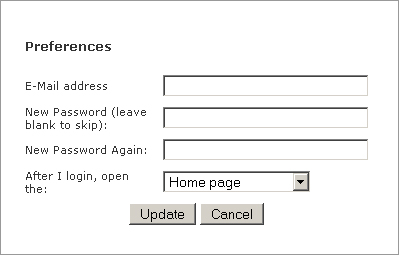
To change your password, type your new password into the two password fields and click Update.
If you do not supply two matching passwords, you receive the following error: The password(s) you entered do not match. Please try again.
To set the page that displays when you login to NaviGo Portal, choose the page from the drop down list and then click Update.
Logging out of NaviGo Portal
When you have finished using NaviGo Portal, you should logout.
To logout of NaviGo Portal, click the Sign Out link in the top right hand side of the screen.